I am working on a DB Drive 1200 that the power supply mosfets were bad changed and would power up ( with current limiter ) and would go in to protection . Removed rectifiers and powers on and no high current draw. Put back in the rectifiers and the protection light comes on . Took out the output drive boards still in protection . put back in the drive boards . Bypassed the protection on the 494 , turned on high current draw , but when I remove the outputs everything is ok ? All the output transistor test OK good ? Thank you in advance , Hector .
Have you checked all of the outputs to confirm that none are leaking (electrically)?
Does this amp use an LM361 (on the driver board behind the RCA jacks)?
Are the driver boards in sockets or are they soldered into the main board?
Does this amp use an LM361 (on the driver board behind the RCA jacks)?
Are the driver boards in sockets or are they soldered into the main board?
How do I mesure outputs for leakage ?
No sure Will check later on , alot of work here at the shop .
Yes soldered to main board , ugh I hate them .
No sure Will check later on , alot of work here at the shop .
Yes soldered to main board , ugh I hate them .
ChipQuik makes getting those types of boards out quick and easy.
If they're not shorted, check for continuity from the gate (leg 1) to the other two legs. You should read an open circuit (meter set to ohms). If any read anything other than an open circuit, they are defective.
If they're not shorted, check for continuity from the gate (leg 1) to the other two legs. You should read an open circuit (meter set to ohms). If any read anything other than an open circuit, they are defective.
LOL just saw a youtube video about ChipQuik that stuff works ! Will order next time from digikey , Thanks .
Ok I will check on that , makes sense to . I was thinking that I should just order some news for that reason of not being 100% sure. Yes I tested them with diode mode like your web page says to . I didnt know about how the mosfets set to ohms should read open to all other pins . Will report back later . Thank you.
Ok I will check on that , makes sense to . I was thinking that I should just order some news for that reason of not being 100% sure. Yes I tested them with diode mode like your web page says to . I didnt know about how the mosfets set to ohms should read open to all other pins . Will report back later . Thank you.
When using CQ to remove driver boards, use the following procedure:
Using this method, you'd apply flux to all of the solder connections and then apply enough CQ alloy so that ~1/2 of the pins of each 5-6 pin group are bridged. After you've applied the alloy, touch your iron to the tip of each pin and heat it until you can move the pin around in the via. Do this for all pins. This helps to promote the mixing of the alloy and the standard solder through the depth of the via. There should still be sufficient alloy on the pins so that ~1/2 are bridged. Now, run your iron back and forth across the pins (not touching the pads). Stay on each group for 3-4 seconds then move to the next group. Two groups are generally the limit when you only have one iron. Go back and forth between the groups of pins. GENTLY try to move the board. When all of the pins are moving, begin to pull the vertical board away from the main board. When done properly, the vertical board will pull out with absolutely no damage to the vias or pads in the main board.
Using this method, you'd apply flux to all of the solder connections and then apply enough CQ alloy so that ~1/2 of the pins of each 5-6 pin group are bridged. After you've applied the alloy, touch your iron to the tip of each pin and heat it until you can move the pin around in the via. Do this for all pins. This helps to promote the mixing of the alloy and the standard solder through the depth of the via. There should still be sufficient alloy on the pins so that ~1/2 are bridged. Now, run your iron back and forth across the pins (not touching the pads). Stay on each group for 3-4 seconds then move to the next group. Two groups are generally the limit when you only have one iron. Go back and forth between the groups of pins. GENTLY try to move the board. When all of the pins are moving, begin to pull the vertical board away from the main board. When done properly, the vertical board will pull out with absolutely no damage to the vias or pads in the main board.
Have you checked all of the outputs to confirm that none are leaking (electrically)?
Yes (2) 9540 and (2) 640 . Iam so happy now I know how to turn them on and now how to check for leakage . Thank you, Perry .
Does this amp use an LM361 (on the driver board behind the RCA jacks)?
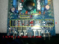
Righ behind the RCAs are NJM2068LD JRC3004G (8) , A3003B 16 pin (1) , TL072 smd 8 pin (1) , and one on each drive board A393F 8 pin .
Ok put in place (2) 9540 and (2) 640 outputs good mosfets , now Iam getting hi pitch sound from the power supply mosfets and the led protection led and the on led light (good led) flashed bright and dimmed out burning the both of them . I removed the power led light and it has ground but the + positive side has 43 plus volts ?? Its connected to one end of a zener diode (good) and then to a resistor (good) and then to a mylar cap 9 (it has the 43plus voltage on both sides) then ends at the 2nd transformer side (postive side) ..??
Im thinking some of the power supply mosfets are burned out. I am going to take them out will post whats the deal with that sound ?.
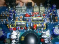
Can you post a photo of the driver board directly behind the RCA jacks? I need to see the components on the driver board.
To clarify, with the two driver boards (parallel to the row of outputs) out of the board and the inputs in the board, it draws excessive current but it draws no excessive current when the outputs are out of the circuit.
This amp does use the LM361. It's the B52 IC.
This amp does use the LM361. It's the B52 IC.
Ive taken everything out output drive boards , the board with the 13600, and the board with the F-16 and the B-52, and they do not stop the hight current draw , but as soon as I remove the outputs 9540s, 640s it idles and the the power led turns on bright no more high current draw. The regulators have correct voltage , but when I install the outputs everthing goes to .330 volts on the output side . I am stuck there ? Any ideas ?
Can you measure the voltage from leg 1-3 on the outputs when it's drawing current (no driver boards in place)? Do all read 0.000v DC?
9640 1. 55.0v 2. .000v 3. 55.3v
640 1.-55.1v 2. .000v 3.-55.4v
with output drive boards out ,and outputs in .
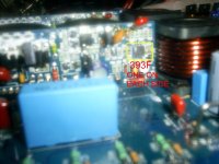
I was looking at one of the drive boards. I thought one part was a smd cap, but it was a smd resistor it changed from black green to a light white color . Compared to the other drive board the numbers of the parts are the same. It looked like the resistor unsoldered it self a bit cause it is alil lifted from the board but still in place and soldered, and around it was a resin-ish brown color on that spot on the board ( clean now ). The outputs look good so it is going to be a part on the drive boards ? Probably the board with this damage huh ?
640 1.-55.1v 2. .000v 3.-55.4v
with output drive boards out ,and outputs in .
I was looking at one of the drive boards. I thought one part was a smd cap, but it was a smd resistor it changed from black green to a light white color . Compared to the other drive board the numbers of the parts are the same. It looked like the resistor unsoldered it self a bit cause it is alil lifted from the board but still in place and soldered, and around it was a resin-ish brown color on that spot on the board ( clean now ). The outputs look good so it is going to be a part on the drive boards ? Probably the board with this damage huh ?
Last edited:
It was real late when I was doing this , thats as far as I got . I ve gotta check out the drive boards parts . All the zener doides check out ok , but as far as the 393 and the transistors do I check those on the board and how ? Thank you .
The problems are typically on the driver boards near the outputs when the outputs have failed. The ktc1027 and kta1023 fail often as well as the 1 ohm resistors. I don't think I've ever seen the driver boards you have so they may be a bit different.
- Status
- Not open for further replies.
- Home
- General Interest
- Car Audio
- DB Drive 1200