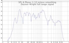
Here's a trace for a 1984 Dayton-Wright ESL more-or-less XG-10 with a full-range signal input. The speaker was sold with a booster tweeter although this trace doesn't include one (which should be apparent). Earlier models with similar panels didn't need extra tweeting.
The box resonance is just south of 80 Hz. With no sub, these have pretty handsome bass. I think as a result of the cleanliness of the sound, it gives your ear no clue when your ear is adding the fundamentals back in... that's my theory.
REW software, RS SPL meter with correction, 1/12 8ave smoothing.
Traces for this speaker as I currently use it tri-amped appear in another thread, post 1394.
http://www.diyaudio.com/forums/subw...all-subs-geddes-approach-140.html#post2441675
Attachments
Last edited:
I certainly enjoyed the 2 systems of the guys i sold XG8s (late 70s, one set was a stacked pair).
dave
PS: i fixed your link.
dave
PS: i fixed your link.
Thanks for link help.
Yeah, I'm a big fan of these speakers, and on a good day, the many imaginative products of this mercurial man. The size of these speakers and their 17kv bias supply make other drivers with puny 1 or 2 mm spacing seem, well, puny. Pity their heyday was before amps putting 400 watts into 2 ohms were easy to find*. I have a few dozen spare elements sitting in a trunk that I might turn into a "wall of sound" some day.
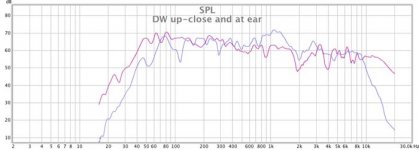
I neglected to say this curve is at 2 meters (79 inches) where my head ordinarily is, both speakers playing.
(Maybe I can figure out how to do one of those anechoic-like up-close time-gated curves to reduce room influence on the mic.)
*Tri-amping, even leaving the ESLs a quite wide and seamless 5 8aves across the middle, greatly helps the amp challenge - not to mention the sound as a whole. Even so, I am sometimes pumping big gobs of power using my Kenwood Basic class-G M2A, with 525 momentary watts per channel into 4 ohms.
Yeah, I'm a big fan of these speakers, and on a good day, the many imaginative products of this mercurial man. The size of these speakers and their 17kv bias supply make other drivers with puny 1 or 2 mm spacing seem, well, puny. Pity their heyday was before amps putting 400 watts into 2 ohms were easy to find*. I have a few dozen spare elements sitting in a trunk that I might turn into a "wall of sound" some day.
I neglected to say this curve is at 2 meters (79 inches) where my head ordinarily is, both speakers playing.
(Maybe I can figure out how to do one of those anechoic-like up-close time-gated curves to reduce room influence on the mic.)
*Tri-amping, even leaving the ESLs a quite wide and seamless 5 8aves across the middle, greatly helps the amp challenge - not to mention the sound as a whole. Even so, I am sometimes pumping big gobs of power using my Kenwood Basic class-G M2A, with 525 momentary watts per channel into 4 ohms.
Last edited:
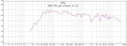
Here is a trace taken an inch from the grill cloth.... OK, I poked around till I had a really nice curve but didn't "cook" it otherwise. Full-range input to a single Dayton-Wright, 1/12 8ave smoothing, which provides about the right degree of meaningful data and not too much meaningless micro levels. At least to my eyes.
The results are within a few dB or my house-curve (or the theatre X-curve) from 42 Hz to maybe 15 kHz, more or less. Pretty nice for an old speaker or a new one.
The second attachment shows yesterday's ear-location curve (both speakers) compared to the up-close curve. Is one curve more valid than the other? One sure is prettier than the other.
Attachments
Last edited:
Here is a trace taken an inch from the grill cloth.... OK, I poked around till I had a really nice curve but didn't "cook" it otherwise. Full-range input to a single Dayton-Wright, 1/12 8ave smoothing, which provides about the right degree of meaningful data and not too much meaningless micro levels.
Hello bentoronto,
Very nice near field measurement 🙂
The first thing I noticed was the absence of any high-Q resonant peak near the bottom of the LF bandwidth. You mentioned a resonance of 80Hz in post #1 but it is barely a blip here with useful LF extension nearly on octave lower. I read somewhere that the transformer primary inductance was resonated with a capacitor to produce a low Q circuit at about 45 Hz to lift the response...perhaps that is what we are seeing.
Do you know how the diaphragm resonance is damped? Is it just from the use of the heavy SF6 gas? or is there damping material applied near the stators. Or electrical notch filter perhaps?
Speaking of the SF6 gas, is the speaker filled such that the internal pressure puffs the front and rear gas containment diaphragms outward? How do you know if some of the gas has leaked out and you are in danger of arcing.
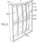
Is it easy to get the grills off of your XG-10s? would love to see a pic of the inner workings.
I'm assuming it is similar to that attached pic I grabbed from the D-W patent.
My apologies for all the questions...kept meaning to ask you for some details on your rather uniquely designed ESLs and kinda just all came out in one post 😀
Attachments
TThe size of these speakers and their 17kv bias supply make other drivers with puny 1 or 2 mm spacing seem, well, puny.
Any idea what the diaphragm to stator spacing is on your panels? Wiki says 0.2" = 5mm. Does this sound correct?
Two other FR ESLs I know of that used similar sized D/S spacing:
- The SoundLab A-1s I got to inspect have D/S = 6mm and run the HV bias at about 14kV.
- The KOSS 1A woofer panels have triple diaphragms with D/S = 7mm. HV bias is run at a lowly 7.5kV but they get the force generated for 22.5kV since they have three diaphragms pushing in tandem. This is another way besides the use of SF6 to get higher efficiency. The only drawback to this technique besides the complicated construction is that the spaced multiple diaphragms limit the HF bandwidth.
Many good questions from Bolserst. Here are today’s best answers.
The panels used in the XG-10 are a bit evolved from those of earlier models. There’s a mysterious perforated metal (reinforcement?) plate. Frankly, I prefer the earlier models because they have better treble and don’t need an auxiliary tweeter. But then beaming needs to be addressed.
It has been a while since I peeked inside an XG-10 and so my comments are based on my collection of earlier panels.
The HV is rated something like 17kV, but I used to keep it lowish in the summer and bit higher in the winter. Which means re-adjusting the amp gains. I used a DW bias supply on my direct-drive amp and the amp added 2.4kV B+ to the stators and then maybe -10kV bias. I can’t remember values when I used the direct-drive amp with free-air DW panels.
As best as I can measure it, the spacing is 5 or 6 mm each side of the membrane. Could be less or more. That’s big but shouldn’t that lead to a cleaner output and bigger maximum output? Whatever words of theory, I might hear from the True Believers in Engineering, there’s something to be said for big gaps.
My speakers have never had their gas seal compromised, that I know of, and there are no sparks in humid weather. And I don’t plan on having cats around ever.
The sealing membranes move in and out with the seasons - I don’t know why and it isn’t just room temperature. Currently, -20C (-5F) out of doors, and they are sucked in an inch or two at the centre, maybe more. In August, often popping out an inch or two. About 5 times over the years, I’ve turned them upside down and bled the air (the gas falls and the air rises - so only air evacuates) to avoid rupturing the envelope film.
Listening to glide tones, I thought I sensed a peak at 80 Hz and decline below. Indeed, that would be true of the curve of my present listening position. You may be right about the basic, gas-filled resonance of the whole box as being 45 Hz. They make pretty nice full-range speakers, unless you are keen for the top treble and bottom bass (and you’d have to add both since it sounds bad to add just one or the other to a speaker). Funny thing, full range they certainly don’t have ESL sizzle or any boom in the bass: they are, in fact, about as characterless as any speaker could be. But my Dennesen tweeters can add all the sizzle I can handle.
Depending on the room, I sometimes have them a foot off the carpet and sometimes with a 4 x 4 foot absorbent panel behind. In the present small damped room, just 2 inches off the carpet and angled up a bit!
I have given some thought to the gas concept. If you have certain ambitions, it is brilliant trick. But for ordinary domestic ESLs, the drawbacks are too much.
Interesting…I figured with the ESL assembly operating inside a sealed bag you would be able to keep the HV bias set the same no matter what the humidity was outside the bag. Good point to know.The HV is rated something like 17kV, but I used to keep it lowish in the summer and bit higher in the winter.
Besides the obvious thermal expansion/contraction of the SF6 that you noted, could also be seasonal change in barometric pressure perhaps? When you are playing music loudly with lots of LF energy, how much excursion do you see in the sealing membranes?The sealing membranes move in and out with the seasons - I don’t know why and it isn’t just room temperature. Currently, -20C (-5F) out of doors, and they are sucked in an inch or two at the centre, maybe more. In August, often popping out an inch or two.
I scanned thru the D-W Patent US3778562 and noted a mention that the resonant frequency with ESLs in the heavy SF6 gas is very low and in fact can be set subsonic. This might explain the non-peaky nature of your near field measurement. Most ESL dipole panels when swept downward in frequency will have an extremely obvious resonant peak unless some form of damping is used.Listening to glide tones, I thought I sensed a peak at 80 Hz and decline below. Indeed, that would be true of the curve of my present listening position. You may be right about the basic, gas-filled resonance of the whole box as being 45 Hz.
Yes, what there is to be said for big gaps is that they are required for Full Range ESLs if you plan on putting out any useful SPL level at low frequencies. 😉As best as I can measure it, the spacing is 5 or 6 mm each side of the membrane. Could be less or more. That’s big but shouldn’t that lead to a cleaner output and bigger maximum output? Whatever words of theory, I might hear from the True Believers in Engineering, there’s something to be said for big gaps.
Theory and practical experiment absolutely agree concerning gap and SPL. As I’ve mentioned before, I built test panels with 1/16”, 1/8”, and 1/4” gaps to test the Baxandall theory that the max SPL and efficiency for ESLs is dependent only on Area and the Breakdown Voltage Gradient of the gas in which they are operating. Gap size only determines how low in frequency you can put out this max SPL. From reading Sander’s book I was originally under the impression that smaller gaps always led to higher output. But, this is only true if you don’t have the capability to design a step-up transformer to match the gap. I think you are probably the only person I have run in to that believes the opposite, that larger gaps lead to higher SPL capability.
For hybrids you simply don’t need the excursion capability.
I see no reason for using gaps larger than 1mm – 2mm in hybrid ESLs.
You gain nothing by using larger gaps besides the headaches of designing a higher step-up ratio transformer and insulating things properly to keep the higher voltages from going where they shouldn’t.
For full range ESLs on the other hand, large gaps are absolutely necessary as they define your low frequency output capability.
Many changes (and production goofs) over the years, but to the best of my knowledge (until corrected by wiser people):
1. gas bag is mylar and glues resemble Pliobond contact cement - good at keeping SF6 inside and but some slight permeability to humidity; not sure I've ever heard sparking, not sure summer is worse, and not sure how damaging it is, and if there are holes in the diaphragm I am not sure how fatal that is, but I superstitiously lower the bias each summer
2. never played these speakers much without the grill cloth (which sits about an inch from the "bag"); my guess is you could readily see/feel it vibrate just as you can see light interference on a diaphragm
3. expansion of gas bag seems seasonal, not just momentary temperature expansion or weekly barometric pressure
4. my many opinions on ESL theory are entirely amateur! a big gap (which of course needs a big bias voltage) is needed for moving lots of air on loud sounds, likewise in my amateur view, a big driver loafing is better than a small driver working very hard,or at least that is the case when you are shaking blocks of cardboard to make sound as with Rice-Kellogg devices, but certainly no need to have too much gap (my Dennesen tweeters have maybe 1 mm)
5. having tested lots of matching transformers long ago, and feeling the magnificent weight of two 39 lb transformers in the DW box, I am very skeptical about the little mains toroids the DIYers are using today, can somebody show me evidence these work well compared to a Dynaco Stereo-70 tube transformer hooked up backward
Last edited:
But what good is a big gap if you can't produce enough force on the diaphragm too move it very far. Perhaps if you think about the fact that the bias voltage is only half of the equation. Force on the diaphragm is proportional to (Vbias)*(Vstator)/(gap^2). If you double the gap and then boost the bias voltage to the point of ionization in the gap you will still lose 6dB of output capability. This means that at a given frequency the diaphragm will only move half as far as it did in the smaller gap. You would need to double the drive signal to the stators as well to gain back the lost output capability. That is the hard/expensive part about increasing gap size...building/buying a transformer with a higher step-up ratio that will still operate over the bandwidth you desire.4. my many opinions on ESL theory are entirely amateur! a big gap (which of course needs a big bias voltage) is needed for moving lots of air on loud sounds
I'd agree that in general for a given output, large area with small excursion tends to produce lower distortion output with fewer extraneous noises than a small area with large excursion.likewise in my amateur view, a big driver loafing is better than a small driver working very hard,or at least that is the case when you are shaking blocks of cardboard to make sound as with Rice-Kellogg devices, but certainly no need to have too much gap (my Dennesen tweeters have maybe 1 mm)
5. having tested lots of matching transformers long ago, and feeling the magnificent weight of two 39 lb transformers in the DW box, I am very skeptical about the little mains toroids the DIYers are using today, can somebody show me evidence these work well compared to a Dynaco Stereo-70 tube transformer hooked up backward
The mains toroids that folks are using work well for hybrid ESLs because their winding geometry has low leakage inductance. This is partly because they have fewer primary turns than the ST70 backwards transformer arrangement and partly because of the longer winding length afforded by the toroidal core shape. However, your ST70 transformers will be able to drive the ESLs lower in frequency and higher in output before the cores saturate.
Last edited:
Appreciate these points, thanks.
It is true that you need the driving force, but if you only have 2 mm of spacing, the only sound you hear will be sparks if you push for greater than a mere 2 mm of movement! Not to mention wind, resonance, departures from flathood, and other normal perturbations of the film. In general, easier to ramp-up the electrical stuff like bias and drive than the mechanical stuff.
About the little mains-power toroids, what kind of frequency response do they have? And given the big power we push into our ESL transformers, at what point do they poop-out? I won't even raise any questions about their voltage insulation! My purpose is not to be mindlessly critical but to wonder if the transformers aren't the weak/cheap link in DIY ESL systems?
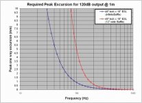
Take a look at the attachment to get an idea of the required peak excursion for 120dB output from a typical DIY ESL panel. As you can see, even with a small 12" baffle width the required peak excursions above 300Hz is less than 0.25mm. Granted most ESL won't be cable of reaching 120dB before the air breaks down in the gaps, but you get the idea. For hybrids crossed over above 250Hz you just don't need much excursion capability. The main reason to use 1mm - 2mm spacing is for ease of construction and to provide some room for the motion of the diaphragm at resonance if you choose not to apply any damping or electrical notch filter.It is true that you need the driving force, but if you only have 2 mm of spacing, the only sound you hear will be sparks if you push for greater than a mere 2 mm of movement! Not to mention wind, resonance, departures from flathood, and other normal perturbations of the film. In general, easier to ramp-up the electrical stuff like bias and drive than the mechanical stuff.
All of the mains-power toroids I have measured provided a flat frequency response out to 40kHz or more with a typical 1000pF ESL load. The 50VA size that is popular has about 0.75in^2 core with about 2000 turns for the 230V winding arrangement and about 50 turns for the 6V windings. So, if you cross at 350Hz, as most people do, you won't run into core saturation issues till you drive it with more than 40Vrms or about 200W into 8ohm. If you try to cross lower, these transformers will start to be the limiting factor as the cores will saturate at lower input voltages and limit your SPL capability.About the little mains-power toroids, what kind of frequency response do they have? And given the big power we push into our ESL transformers, at what point do they poop-out? I won't even raise any questions about their voltage insulation! My purpose is not to be mindlessly critical but to wonder if the transformers aren't the weak/cheap link in DIY ESL systems?
The voltage insulation between primary and secondary is usually rated at 3000Vac or higher, so is adequate.
However, if the 230V winding is made up of two parallel wound 115V windings the insulation between these windings may be a weak link.
Attachments
Last edited:
All very helpful information. Thanks.
While 120 dB is pretty loud, a crossover at 250 Hz at lower levels can still mean substantial driving signal at 125 Hz and below. And on top of that, construction irregularities, wind, dust, pet hair, shredded vinyl from record jackets, etc.
I'm not sure what the two curves represent in the attached chart.
While 40v at 8 ohms is a familiar rating, ESLs can be a whole lot different than that and might have considerable amps at low impedance. It would be nice to see performance specs with the little toroid(s) in action. I've not heretofore had the means of 'scoping directly to the stators - can that be done? Should the voltage input be flat for flat output?
One of my favourite speakers of all time. I liked adding a Decca Ribbon tweeter to the XG-8's. You can generate tremendous SPLs if you want with the Dayton-Wrights, given gobs of power (eg two 4B's in mono).
Possibly the world's best test device for amplifier stability ... I found Bryston 4B and Threshold amps fared well (in the day), but if you hooked up something like a Phase Linear 400 ... near-instant amplifier self-destruction.
Possibly the world's best test device for amplifier stability ... I found Bryston 4B and Threshold amps fared well (in the day), but if you hooked up something like a Phase Linear 400 ... near-instant amplifier self-destruction.
Last edited:
If ESLs are crossed over with at least 12dB/octave slopes the drive signal is reduced at the same rate that the excursion goes up. So, you will not require any extra gap capability below crossover. That being said, because of construction irregularities and other unknowns you mentioned (and the diaphragm resonance i mentioned previously) the recommended gap size for hybrids is 1mm - 2mm. BTW, in reality the air in the gap will start to conduct once you get much past 110dB so figure actual required excursions are a third of those plotted in my previous post.While 120 dB is pretty loud, a crossover at 250 Hz at lower levels can still mean substantial driving signal at 125 Hz and below. And on top of that, construction irregularities, wind, dust, pet hair, shredded vinyl from record jackets, etc.
The blue curve is the required excursion for 120dB if the ESL panel was mounted in an infinite baffle.I'm not sure what the two curves represent in the attached chart.
The red curve is the required excursion for 120dB if the ESL panel was mounted in a 12" wide baffle and the panel has to make up for the dipole cancellation below 550Hz.
Yes, you can use a HV(1000 Megohm) probe to monitor the stator voltages directly.While 40v at 8 ohms is a familiar rating, ESLs can be a whole lot different than that and might have considerable amps at low impedance. It would be nice to see performance specs with the little toroid(s) in action. I've not heretofore had the means of 'scoping directly to the stators - can that be done?
Measured response is flat until you reach resonance at about 40Khz.
Then the roll off behavior depends on the value of damping resistor you have in series with the primary winding.
The low impedance point for ESLs driven with these toroids occurs at the 40kHz resonant frequency.
The transformer doesn't have any issues with this, but the driving amplifier might as the impedance usually dips down to 1 ohm or so in the top octave and has a highly capacitive phase angle with can cause instability in amplifers and may also drive output transistors outside of their SOA ratings if not properly designed.
Last edited:
After a spell with my own matching transformers and various tube and transistor amps and then my own high voltage Sanders-like direct-drive amp, I've been driving my DWs with stuff that would get me evicted from any gathering of HiFi enthusiasts*. Currently, Kenwood Basic M2A, Class G, 530 "dynamic" watts, from about 1982 (I also use one of these swell jobbies on my ESL tweeters, north from 3200 Hz - no kidding).
Once you eliminate the upper and lower octave and a half, no problem driving them or even full range. Bryston started that rumour.
The later DWs needed tweeter enhancement. Mike Wright said from 8-9 kHz. Sure, like my old ears need half-an-8ave! If you have a good tweeter array, good reasons to cut in lower. I give my ESL tweeters about two octaves (at least that's all that matters to me since I don't have a dog). Mics seem to find good output above that. I wouldn't know.
Back to gaps: to spec a gap, you add together excursion, voltage breakdown at max excursion, construction irregularity, resonance, dog hair...... and then add a substantial margin for error and another margin for safety**. Not easy to get all that into a mm or two. Granted, it is done all the time.
*1970s JVC receivers.......
** Oh yeah, what about rainy weather?
Last edited:
Back to gaps: to spec a gap, you add together excursion, voltage breakdown at max excursion, construction irregularity, resonance, dog hair...... and then add a substantial margin for error and another margin for safety**. Not easy to get all that into a mm or two. Granted, it is done all the time.
** Oh yeah, what about rainy weather?
Yup, 1mm - 2mm gaps are used all the time for hybrids(both DIY & commercial).
They are reliable and play loudly without needing transformers with unusually large step-up ratios or amplifiers with unusually large output capabilities.
Since humidity reduces the allowable voltage gradient before breakdown, it affects all gap sizes similarly(reducing output capability by the same ratio).
So going to a larger gap does not buy you any relief from humidity affects.
That was one reason I was interested in the D-W approach of bagging the panel in a known gas mixture.
I didn't realize that the sealing diaphragm was thick enough to keep the SF6 in, but not necessarily able to keep humidity out.
I didn't realize that the sealing diaphragm was thick enough to keep the SF6 in, but not necessarily able to keep humidity out.
That's what they say, 20 yrs for the gas and very small migration for humidity. I couldn't say myself, except there is the change in pressure around the year cycle. Mylar they say.
For sure, the SF6 is a clever idea. But is it sound to "bag" a technology respected for sparkling cleanliness?
The construction standard is good. A Quad (and others) looks like amateur one-off garage projects next to the DW. The panels are marvels of solidity and strength and mounted in formed frames inside welded boxes. Likewise the electronics, cables, switches, very fancy plugs (like all his electronics which are revered to the same extent) and for good reason. They are more like MIL-SPEC than hifi-spec. BTW, except for the panels which I greatly cherish (even inside a "bag"), I am by no means a Dayton-Wright fan-club fanatic, just an occasional owner and admirer of his pre-amps, graphic equalizer, and super-duper moving coil pre-pre-amp.
Last edited:
I had XG8's back in the day and I later had them upgraded to XG10's. Absolutely fantastic speakers. I loved them dearly. They even survived a move from Montreal to Sunnyvale.
You guys really should get Nelson Pass over here to join in. Back in the day he published a white paper or two on modding these speakers. The basic mod removed all of the filters and Mike Wright phase-shift stuff from the transformer primary circuit and a second mod, as I recall, used an op-amp circuit to put feedback around the transformer. My memory of these mods is dim being that so much time has passed. But the mods seriously clarified the sound.
Nelson shared a story (it's on the site here somewhere) of Joe Sammut inhaling the SF6 gas as a party joke. It has the opposite effect of helium.
I still have my super-duper pre-pre amp (the DW-535) but I haven't fired it up in ages.
It's nice to see yet another MW appreciation thread. Definitely an original thinker.
Graeme
Last edited:
Mike Wright actually got me going in this ESL hobby.In the 70s I decided to build the Sanders electrostatic speakers that were in Audio Amateur . Trying to track down the 1/4 mil Mylar film was proving to be very difficult .I finally spoke to someone at Dupont who knew what I was talking about and he said he had a customer that used that film and why don't you call this company ,Dayton Wright, and maybe they will sell some to you.I had never heard of the company before . I called the next day and the guy on the phone says sure come down to the factory after hours and we"ll see what we can do.After work I drove to a factory in this dingy industrial area and was met at the door by this portly gentleman who introduced himself as Mike Wright.I explained that I was building some electrostatic speakers and he said follow me and whizzed off at a frantic pace into this dark deserted factory.His first stop was at this huge roll of Mylar .He pulled off about 30 yards of the film hands it to me and says"you'll need this " .He then races off into the dark factory and I follow as he hands me some other parts that I will need .All the while he is talking about electrostatics,his days at MIT and early experiments in electrostatic speaker construction most of which went way over my head. Then on to another room with these giant electrostatic speakers and a big but well worn easy chair .I had never heard anything in my life like those speakers.After an hour or so we boxed up all the goodies he had given me and I asked what I owed him and he said" forget it kid "and off into the night I went .I'll never forget the kind man who took the time to help a struggling amateur .
Andrew
Andrew
- Status
- Not open for further replies.
- Home
- Loudspeakers
- Planars & Exotics
- Dayton-Wright XG-10