Or go balanced. Plug and play, no interference (if you do it right). FWIW even with short links I use these https://www.neutrik.com/en/neutrik/products/xlr-connectors/xlr-cable-connectors/emc-series . They are a royal PITA to assemble is the only downside.
Oh, to me they are the easiest to work with that I know of. And a dream to solder.
You need a little practice I guess. 😉
Hugo
You need a little practice I guess. 😉
Hugo
I am not sure what this really means (55-60dB CMRR?), but I now have pretty even looking CMRR from my transformer, by using 2 in series, to significantly reduce the stray capacitance. Yellow trace is it doing its transformer thing with unbalanced signal between inputs, green trace is 2 inputs shorted together and unbalanced signal connected between shorted inputs and ground. I have also now got a buffered multi turn null pot.... Seems to work ok.

https://www.analog.com/media/en/training-seminars/tutorials/MT-042.pdfI am not sure what this really means (55-60dB CMRR?)...
https://en.wikipedia.org/wiki/Common-mode_rejection_ratio
Also, instead of using two transformers, you might try one transformer with an electrostatic shield between the primary and secondary windings. Often its capacitive coupling between the two windings that is the problem. A shield can reduce the coupling substantially.
In the transformer model below, C3 is the capacitance that may be reduced with a shield:
Last edited:
Hi, thanks. I do know what cmrr means 🙂, it was more like how useful that amount of cmrr would be for my experiment and is it actually real world real.
To make my first attempt better I tried putting a CM choke in before the transformer first but it didn't really help in the audio band, so I had a go at simulating. The first transformer was very uncooperative. So I figured I should try a different one, I had some which wer a bit lower capacitance, and with 2 in series I got the C down from 350pF, to about 35pF.
I will keep my open for I e with electrostatic screen. I will check actually the ones I have may have one already.
OEP A262A2C are indeed screened 🙂. I have 2 in series 🙂. These have been sitting in my draw of useful parts for almost 30 years, waiting for this moment....
Last edited:
Sorry to say, but this sort of CMRR is not impressive. With balanced connections and a buffered instrumentation amp figures between 100 and 120dB in the audio band are easily achievable.I am not sure what this really means (55-60dB CMRR?), but I now have pretty even looking CMRR from my transformer, by using 2 in series, to significantly reduce the stray capacitance. Yellow trace is it doing its transformer thing with unbalanced signal between inputs, green trace is 2 inputs shorted together and unbalanced signal connected between shorted inputs and ground. I have also now got a buffered multi turn null pot.... Seems to work ok.
View attachment 1223195
Hans
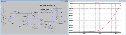
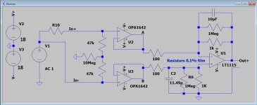
To give you some confidence in what I mentioned in the previous posting, I have made a simulation with low noise Fet opamps.
Since you have to measure CMRR with two different cables, the receiver should have a high impedance to prevent reducing the CMRR because of differing cable impedances.
First image shows that tuning R6 (not needed here) and C2 from 10pF in Red to 10.13pF in Blue makes the CMRR flat over the band to 20Khz close to 120dB,
C2, should be a 7.5pF cap in series with a 5pF trimmer, here adjusted to 10.13pF to flatten CMRR at 20Khz.
R6 should be a 953K resistor in series with a 100K ten turn trimmer to reduce CMRR at 100Hz.
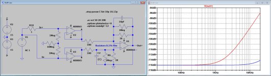
The second image shows the negative effect on CMRR when one cable has 1R more resistance as the other one.
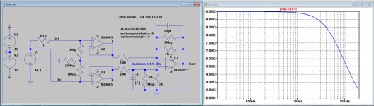
Third image shows the input impedance of the proposed circuit diagram.
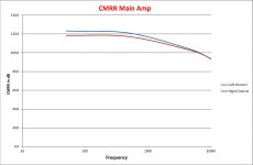
Fourth image shows the measured CMRR of my balanced main amp, modelled in the same topology, just to prove that the simulation doesn't produce nonsense.
Hans
Since you have to measure CMRR with two different cables, the receiver should have a high impedance to prevent reducing the CMRR because of differing cable impedances.
First image shows that tuning R6 (not needed here) and C2 from 10pF in Red to 10.13pF in Blue makes the CMRR flat over the band to 20Khz close to 120dB,
C2, should be a 7.5pF cap in series with a 5pF trimmer, here adjusted to 10.13pF to flatten CMRR at 20Khz.
R6 should be a 953K resistor in series with a 100K ten turn trimmer to reduce CMRR at 100Hz.
The second image shows the negative effect on CMRR when one cable has 1R more resistance as the other one.
Third image shows the input impedance of the proposed circuit diagram.
Fourth image shows the measured CMRR of my balanced main amp, modelled in the same topology, just to prove that the simulation doesn't produce nonsense.
Hans
Attachments
0.1% metal films mostly have 25ppm tempco’s.
But while using two pairs of the same 100 and 1k,
tempco differences between them may even be a magnitude lower.
So, IMO not really an issue to worry about.
Hans
But while using two pairs of the same 100 and 1k,
tempco differences between them may even be a magnitude lower.
So, IMO not really an issue to worry about.
Hans
Yes, it is satisfyingly flat though, but this in itself is a problem. That flatness is noise (hum predominantly). It could be better, but it is now good enough to hear the distortion of the amplifier and also to hear it change as the amplifier heats up... It wasn't particularly what I was looking for, but very interesting.Sorry to say, but this sort of CMRR is not impressive. With balanced connections and a buffered instrumentation amp figures between 100 and 120dB in the audio band are easily achievable.
That's is quite impressive. My intellectual problem is that I am hanging my transformer across the speaker terminals of power amplifier and I worry about running out of voltage head room. The totally floating gives me comfort in that area. The opamp approach I may look into If I choose to investigate lower level signals or voltage dropped across wires.Fourth image shows the measured CMRR of my balanced main amp, modelled in the same topology, just to prove that the simulation doesn't produce nonsense.
Hi Damon,
1) Just curious what you mean that the flatness is noise and predominantly hum.
Does this describe the transformer or the opamp version ?
The opamp version as earlier shown will produce 2uV max RTI in the audio band.
I have changed all opamps into lower noise versions bringing the noise RTI to 1uV from 20Hz to 20Khz, see attachment.
Your Focusrite is specified as -128dBU-A, which roughly translates to 0.5uV input noise.
So with this second version, noise will increase by 6dB.
2) What output voltage max can your gainclone produce?
Let’s say +/-35 volt.
The proposed opamp circuit has a gain of 10 and was thought for testing interlinks with acceptable levels up to several Vrms.
But when testing LS cables the two buffers could be omitted and the gain of the amp reduced from 10x to 1x.
With a +/- 18V supply for the remaining opamp, a CM voltage of almost +/-34V can then be processed, similar to your transformer.
But the much higher CMRR enables to work with lower input voltages while at the same time being able to look with a much higher sensitivity at the differences produced between the two cables.
So when using the circuit as proposed, your max input voltage has to be 6dB lower but your CMRR will be at least 60dB higher.
Hans
Attachments
Hi Hans
The alternative is the OPA 1612, which has a factor of 5x lower input noise (1.1nV/rootHz) than the OPA1642. And much lower 1/f knee. Within spitting distance of the difficult to use AD797. I've used the 1612 quite a lot, and although only surface mount, it is a pussy cat to use.
The potential disadvantage is that it is bipolar, not FET, and a FET opamp might be a requirement of your design?
Craig
Hi Craig,
To keep CMRR high, input inpedance must be very high, in this case in the MegOhm region, hence Fet opamps.
Hans
To keep CMRR high, input inpedance must be very high, in this case in the MegOhm region, hence Fet opamps.
Hans
The green trace below is pleasingly flat, but it shouldn't be. I did simulate the two transformers, but unfortunately do not seem to have saved it. What it showed was around -70-80 dB at 20 kHz, but falling off to below -100 dBs as the frequency falls. I suspect this is happening, but is masked by hum on the graph below, green trace.Hi Damon,
1) Just curious what you mean that the flatness is noise and predominantly hum.
Hmm, I think whe gainclone rails are about +/-24 volts. I would not feel happy hooking that straight up to an opamp input running on +/- 18V supply with tenuous ground connections, without some attenuation. I am sure it would give very marvelous results even then.View attachment 1223195
2) What output voltage max can your gainclone produce?
Let’s say +/-35 volt.
The proposed opamp circuit has a gain of 10 and was thought for testing interlinks with acceptable levels up to several Vrms.
But when testing LS cables the two buffers could be omitted and the gain of the amp reduced from 10x to 1x.
With a +/- 18V supply for the remaining opamp, a CM voltage of almost +/-34V can then be processed, similar to your transformer.
But the much higher CMRR enables to work with lower input voltages while at the same time being able to look with a much higher sensitivity at the differences produced between the two cables.
So when using the circuit as proposed, your max input voltage has to be 6dB lower but your CMRR will be at least 60dB higher.
Hans
Would temporarily lowering the gainclone’s supply to +/-18Volt then be an idea ?
You lose a bit but gain a lot 😊
Hans
You lose a bit but gain a lot 😊
Hans
Subsequent to the improvements to my jigs and some further testing, I was about to declare a great victory as I could clearly hear a difference between my low Z and high Z cables (from now referred to Q(ED), high and G(oertz), low) (terminated into 8 ohms) when compared to an unloaded channel. It was quite obvious and I demonstrated to my son, who thought so to. Was mentally writing script for my youtube video announcement in my head...... after a reflection pause, doubts entered my head however, and I decided to do swapping around sanity check.
Glad I did. One channel of the amplifier (R) was unloaded and I swapped the positive of cables Q and G to the other channel. Q and G's ground wires were connected to the L and R's ground pins of the gain clone. This proved to be to be the source of the "difference", unfortunately. The gain clone's wiring probably could be better, I know grounding is a complicated subject. Even though the 4mm ground binding posts were coupled straight to the case, the difference between them was causing the audible difference. Swapping between G and Q's positive and grounds together to the L channel, no difference in sound obvious. I have strengthened the grounding in the gain clone now and it behaves more like one would expect.
So I guess that is a preliminary result.
Sulk. Still to retest with tube amp but it was feeling unhelpful, so put to one side for the time being.
N.B. All above testing with differential taken from L and R's "positive" outputs on the amplifier.
What next?
Easy to do at this place is to replicate Max Townsend's measuring across the ends of the speaker cable, which I have done already. Hopefully my new rig will give some more possible measurement combinations and better results. This type of test is quite easy to do with minimal unbalanced test equipment, as you can measure between the amplifier ground and the far end of the speaker cable "ground".
Good read, thanks. Would be interesting to try some similar impedance measurements on the cables I am testing. Especially interesting his comments on the speaker end termination. I prefer high capacitance cables so I try to make sure my kit can cope, but no actual idea what is happening into the RF.Are you aware of Cyril Bateman's work investigating effects of speaker cables on amplifier stability? If not, he did some measuring but IIRC it wasn't particularly looking for HD/IMD: https://www.waynekirkwood.com/images/pdf/Cyril_Bateman/Bateman_Speaker_Amp_Interaction.pdf
Yes absolutely 🙂 . I am open minded as to whether it is a thing, and have had an "experience" that suggested that it may be, but I have no idea which end of what is what in my current setup, and try not to fight too many windmills at once. For back ground, I have a very complicated hifi set up that requires about 15 mains connections, 4 way semi active etc. I ignore directionality, mains, and supports / racks / stands. Just not practical. Sounds very lovely none the less.Was wire directionality intentionality neglected? All wire/cables sound different one way vs the other. That’s what is referred to as a hidden variable.
- Home
- Amplifiers
- Solid State
- Dave's attempt at a Null test