I did something along these lines with low level interconnects. I was sure I was on to something, but it's all rubbish!
http://www.conradhoffman.com/Low_Level_ICs.htm
Note that I used a triangle waveform, and the reason why. The beauty of a true null test is it isn't very sensitive to the quality of the waveform.
http://www.conradhoffman.com/Low_Level_ICs.htm
Note that I used a triangle waveform, and the reason why. The beauty of a true null test is it isn't very sensitive to the quality of the waveform.
@hbc : It's still not clear to me what you were testing with both music samples? Interconnects, speaker cables, or..?
If both samples are made with just interconnects swapped, I suggest you use a third simple ordinary cable, repeat the test with the 3 cables and post the samples.
I am very curious about the results.
Hugo
If both samples are made with just interconnects swapped, I suggest you use a third simple ordinary cable, repeat the test with the 3 cables and post the samples.
I am very curious about the results.
Hugo
NIce article. If hbc's test is what I suspect -just swapping interconnects - I wonder why plugging the sound files in a DAW gives such a great audible and visual difference. I'd like to compare with the original file but the YouTube audio is too messed up to do anything useful with it.I did something along these lines with low level interconnects.
Note that the last sentence of your article also applies to my way of thinking.
Hugo
Pink noise would be safer for the ears no? Problem with noise is it sounds different versions of bad
Cheers
Cheers
For the apparatus in the diagram below, how did you test can calibrate the apparatus itself?

IOW, how do you know the amplifiers are identical, and or everything else is doing what you expect it to?
Regarding what sort of test signal to use, music or something else that human ear is sensitive to would seem to make the most sense. Humans are very sensitive the voice of someone they know well. Humans are sensitive to certain frequency bands; sensitive to transients, phase, and time-domain waveforms at lower frequencies, etc.
The idea of using an FFT analyzer to measure anything should be considered carefully for pros and cons. Against the proposition is the warning given by Lars Risbo and Bruno Putzeys in their blog at Purifi:
"I’d like to offer up a small demo to caution against this form of Popular Psychoacoustics. Below are two signals whose power spectra are completely identical. Only the phase relationships are different..."
https://purifi-audio.com/blog/tech-notes-1/doppler-distortion-vs-imd-7
Also, some reading material of possible interest attached below.
Attachments

As per circuit above I am attempting to feed an identical signals into two identical power amplifiers. I am then attempting to look for any difference between the two amplifier outputs, using a floating transformer coupled in to the "balanced" input of 2i2, from which I can monitor the null on headphones (and record into PC).@hbc : It's still not clear to me what you were testing with both music samples? Interconnects, speaker cables, or..?
If both samples are made with just interconnects swapped, I suggest you use a third simple ordinary cable, repeat the test with the 3 cables and post the samples.
I am very curious about the results.
Hugo
Initially using dissimilar speaker cables into identical resistive loads, I was hoping to hear a difference between cables but was inconclusive. Upon unplugging one cable and load (the low output z maintains the null), what I think I am hearing is the difference between a loaded and unloaded amplifier output. Which is an interesting result in itself, and on the mp3 first is the difference between a loaded channel with wire and an unloaded channel with no wire, and the other sample is the difference between two unloaded amplifiers. Hope that helps.
I did start using speakers but they were too noisy and I couldn't hear the nulled signal in the headphones.
I am going to do some sanity checks i.e. distortion measurements now to try an establish if what I think is happening is.
If there is a difference in cables, it often has nothing to do with HD/IMD. Beyond that there may be more than one physical effect having some impact on the sound. Therefore distortion measurements are unlikely to show all measurable effects that may be involved. The documents I posted #25 may give you some ideas of what sorts of things to look for, although its probably not a complete list....distortion measurements...
How long were the cables? Do you think length might be an important variable to keep track of? Are you aware of Cyril Bateman's work investigating effects of speaker cables on amplifier stability? If not, he did some measuring but IIRC it wasn't particularly looking for HD/IMD: https://www.waynekirkwood.com/images/pdf/Cyril_Bateman/Bateman_Speaker_Amp_Interaction.pdfInitially using dissimilar speaker cables...
Also, I would just mention that people tried looking for HD/IMD to see if Bybee devices could have any effect on sound. They didn't find any HD/IMD so some people concluded Bybee devices couldn't be doing anything at all. Those same people maybe should have tried measuring some other things before jumping to conclusions.
That was what I suggested in #11. Like any instrument you have to calibrate and finding the borders and limitations.For the apparatus in the diagram below, how did you test can calibrate the apparatus itself?
By calibratingIOW, how do you know the amplifiers are identical, and or everything else is doing what you expect it to?
Very true, but IMHO with this sort of test it will be hard to catch timbre and phase distortion as more or less shown in the video in #1, where are interlinks seem to be equal, because details are lost in noise and phase distortion can't be measured.Regarding what sort of test signal to use, music or something else that human ear is sensitive to would seem to make the most sense. Humans are very sensitive the voice of someone they know well. Humans are sensitive to certain frequency bands; sensitive to transients, phase, and time-domain waveforms at lower frequencies, etc.
Interesting info with the square wave test showing modulation of capacity. I guess that with "Balanced" the author means differential, and what about the step size, equal but in opposite direction, or halve the step size on each side.The idea of using an FFT analyzer to measure anything should be considered carefully for pros and cons. Against the proposition is the warning given by Lars Risbo and Bruno Putzeys in their blog at Purifi:
"I’d like to offer up a small demo to caution against this form of Popular Psychoacoustics. Below are two signals whose power spectra are completely identical. Only the phase relationships are different..."
https://purifi-audio.com/blog/tech-notes-1/doppler-distortion-vs-imd-7
Also, some reading material of possible interest attached below.
Anyhow, balanced cables seem to do a better job 🤣
Hans
Hans,
The first time someone asked me to listen to a cable, it was a differential XLR situation. Guy just said here's a cable, try it when you have a chance. Then he left without saying anything more. Cable was one meter in length. I put off trying it for a few days because it figured it would be a waste of time. However, found out it sounded obviously different from the cable I had been using. I was stunned, was not expecting any difference at all. As a sanity check I made up 5 XLR cables, all the same length, all with same connectors, only the cable was different. There was Belden, Mogami, etc. They all sounded different. Before that when I read that people were wiring recording studio with Mogami cable because it sounded better, I scoffed. Didn't believe it. Now I do. BTW, one cable I tried was from custom made bulk cable that was not jacketed until final assembly.
Mark
Hi Mark,
If not clear, in my reply I was referring to the link with the square wave tests that favoured balanced cables.
In your posting It’s almost as if you are telling that only XLR cables sound different.
But we both know that the same is just as well true for RCA cables.
Hans
If not clear, in my reply I was referring to the link with the square wave tests that favoured balanced cables.
In your posting It’s almost as if you are telling that only XLR cables sound different.
But we both know that the same is just as well true for RCA cables.
Hans
Hi Hans,
Yes, you are correct about RCA. My first realization was with XLR cables, is all. Since then it turned out speaker, headphone, and tone arm to preamp cables are included.
Mark
Yes, you are correct about RCA. My first realization was with XLR cables, is all. Since then it turned out speaker, headphone, and tone arm to preamp cables are included.
Mark
For loudspeaker cables, there can be a meaningful force between the conductors. Of course you can do the calculation and it does not seem significant (milliNewtons per meter), but the anecdote relates to a set up I was doing at an audio show back in the early 90's. The team had designed a Krell killer amp, but with a humongous current driving capability and which didn't blow up if abused.
Wired it up to the high end speakers we were using, with ship's hawser gauge cable, fed music in, and a sound somewhat like a tinny distorted old radio playing somewhere emerged. After some head scratching and panic that we had blown something up, we found that we had shorting links across the speaker terminals. So the sound we were hearing was the loudspeaker cables vibrating in response the current flowing. The amp was in fact playing just the speaker cables into a short circuit.
So we found that you can indeed hear loudspeaker cables. And if they vibrate in a distorted way time to the music they are adding to the sound you hear from the loudspeakers.
Of course this effect is different for every construction of loudspeaker cable, and I would guess that some are more prone to this effect than others. Maybe the ones that vibrate less are the ones that sound the best?
Craig
Not clear if that's the case. Sometimes removing the rubber jacket is beneficial.Maybe the ones that vibrate less are the ones that sound the best?
Indeed, I agree, that is why I am looking for changes in the signal coming from the amplifier.If there is a difference in cables, it often has nothing to do with HD/IMD. Beyond that there may be more than one physical effect having some impact on the sound. Therefore distortion measurements are unlikely to show all measurable effects that may be involved. The documents I posted #25 may give you some ideas of what sorts of things to look for, although its probably not a complete list.
This is the FFT of the null with both channels of the amplifier unloaded at 1kHz, green, and with one channel loaded, pink. Full un-nulled output is a tad below the 0dB for reference. So this I what I could have been hearing in the two sample earlier. I have a better null now. very educational.
First provisional conclusion. My amp is more distorted under load, and I may be able to hear it.
I am not accustomed to listening to distortion of this magnitude, so my brain has some adjusting to do. I am starting to feel the floating differential probe is a handy tool and needs to be boxed and tweaked.
One vital thing to keep in mind: a cable is basically a linear system and as such cannot produce THD.
So when you see THD or IMD it has with a high probability to be the amp sourcing the cable.
But the cable like any linear system may affect overall frequency response and phase thereby causing perceivable differences.
Hans
So when you see THD or IMD it has with a high probability to be the amp sourcing the cable.
But the cable like any linear system may affect overall frequency response and phase thereby causing perceivable differences.
Hans
Hans,
The the extent a cable is a motor as described by sawyers, and or an audio-signal-voltage-dependent capacitor as described in the AES paper, not so sure it is LTI.
Also, connectors have been known to be a source of PIM at RF frequencies.
Moreover, as shown by Cyril Bates, and later by PMA, cable capacitance is to some extent or other part of the amplifier feedback network transfer function.
Mark
Last edited:
Null Tests: While it is similar to a CMRR test, the Freq, Gain, Phase matching is part of the error output signal.
The NULL’s greater than 100 dB can be a problem to achieve. Effects of source Z, Dissimilar metal contacts, contact resistance, Temperature (PPM), VSWR and other can also be an error source.
Our brains can hear signals/errors way below the noise floor.
Try this test. Mix White Noise and music where the music level is well below the noise floor and we can understand it @ -30 dB or better. This is like AM Radio.
Duke
Mark
As Cyril Bates has shown is that HF reflections can be far from harmless, not only perceivably interfering with the audio signal but they can also make an amp unstable or even worse
That’s why interlinks should be driven by 100R, a value that corresponds to the Char. Imp. of most cables, or alternatively terminating the cable with 100R in series with a Cap of proper value.
The same 100R+Cap termination is also beneficial for a LS cable to suppress reflections since at HF the speaker is an open connection.
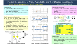
That's why I'm rather suspicious about the Yonega paper showing fluctuating capacitances, because nothing is mentioned about proper termination.
The Capacitance Change images are giving the strong impression that reflections are taking their fair share in the waveforms.
The second reason to be hesitant is pure academic: A test that hasn't been reproduced by an independent instance, has to be regarded with care.
The third reason is that when capacity changes of 0.02pF/meter take place, the effect with a relative low ohmic source will have it's effect in the Mhz region, far outside any reasonable audio range.
Hans
As Cyril Bates has shown is that HF reflections can be far from harmless, not only perceivably interfering with the audio signal but they can also make an amp unstable or even worse
That’s why interlinks should be driven by 100R, a value that corresponds to the Char. Imp. of most cables, or alternatively terminating the cable with 100R in series with a Cap of proper value.
The same 100R+Cap termination is also beneficial for a LS cable to suppress reflections since at HF the speaker is an open connection.
That's why I'm rather suspicious about the Yonega paper showing fluctuating capacitances, because nothing is mentioned about proper termination.
The Capacitance Change images are giving the strong impression that reflections are taking their fair share in the waveforms.
The second reason to be hesitant is pure academic: A test that hasn't been reproduced by an independent instance, has to be regarded with care.
The third reason is that when capacity changes of 0.02pF/meter take place, the effect with a relative low ohmic source will have it's effect in the Mhz region, far outside any reasonable audio range.
Hans
Was wire directionality intentionality neglected? All wire/cables sound different one way vs the other. That’s what is referred to as a hidden variable.
- Home
- Amplifiers
- Solid State
- Dave's attempt at a Null test