Thanks for answers and link,
Peufeu, if you play with the Subbu and the differents BOM, then measure it, tell me please if you are on the same choices I did and if its about pleasant distorsions !
Ah I try to find the ref about a book about harmonics writed by an american lady violins specialist ( from a "La revue de l'audiophile" paper)... I try come back with it tommorow !
A while ago I did some quite extensive simulations of SPDIF interface with different cable lengths, severe impedance mismatches, different rise times very hard to really mess up the signal (even though in some cases it looked rather bad as a waveform) and the waveform soon cleared up with some simple termination...
For SPDIF it's the lowpass effect that matters, ie intersymbol interference, causing data dependent jitter in the recovered clock.
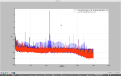
See attached measurement. Cheap CDP, toslink (maximises ISI), connected to Onkyo TX NR 905, very expensive receiver. Alas it has CS84xx SPDIF receiver which has no jitter rejection, and the very good Burr-Brown DACs in it are wasted. Yet another case of $20 ES9023 DAC beats 2000€ receiver. Confirmed by ear, the Onkyo although very nice using any analog source, has unlistenable DACs.
To get to that level of failure, you need to get everything wrong ! Which is the case in this receiver (sadly).
Marce I sent you PM 😉
Attachments
Last edited:
To get intersymbol interference you really have to make a mess of the interface and cabling, never played with Toshlink or used it. But you do have to work hard not to get the signal from a to b.... If you follow some basic digital rules, no problem, its the way overboard solutions etc. that some come up with, they would be better buying some books by Howard Johnson (chapter 6 Terminations), Eric Bogatin etc.
Getting the receiver wrong! is surprising for such a company and disappointing... But having seen photos inside a lot of this kit, I was amazed at the lengths some go to, to save money...
Getting the receiver wrong! is surprising for such a company and disappointing... But having seen photos inside a lot of this kit, I was amazed at the lengths some go to, to save money...
Since a topic about streaming audio with correct bits sounding different depending on gear will inevitably end up about jitter, I think it isn't off topic to post this :
http://www.nanophon.com/audio/jitter92.pdf
(That's the famous article by Dunn).
Ethernet (as many other serial links these days) uses automatic line equalization and scrambling. SPDIF does not.
See fig.3 in the paper for a rather severe lowpass effect in the transmission line, that adds ISI. Since the data isn't scrambled, that adds lots of data-dependent jitter, which is correlated to audio sample values.
In order to get the this spectacular measurement, I have used :
- The crappiest CDP ever, which produces tremendous amounts of jitter on the output.
- Toslink, which produces a lot of ISI because the bandwidth of the receivers is low, plus it has a crummy SNR, so it adds lots of random jitter too.
- An Onkyo with CS84xx SPDIF receiver, which is, as audiophiles say "transparent", it has a wide PLL bandwidth, so all jitter gets through unfiltered.
Of course with a better SPDIF source, better cable etc, this onkyo gets cleaner output (up to a point, it never really works well). Some may argue that, of course, you have to use a very expensive transport and cables etc. In my opinion though, the whole point of digital audio is that if you feed it correct bits then it is supposed to work.
An odd question about I2S transmission line and FIFO please:
If the I2S line between a I2S transmission board and a receiver board with a FIFO+isolator for this last before the dac chip : does a standalone GND wire for return path is enough between the two boardswith a short 10 cm distance between the two boards (instead 3 coax matched impedance cables at 50 ohms like uf-l or some otherd are ?).
FIFO & reshynchronisation + isolator solve this problem of poor interlink connection on short distances (few cm) ?
In an other thread I believe to uderstand than two isolator chips (one per board but PS feeded by the emitter to allow the isolation in relation to the receiver board) can be a source of problem ? (I understood in the case where the isolator on the transmiter boards can not be swaped by design: amready there !)
regards
Eldam
I2S is designed for on board, if going of board each signal needs its own return wire... Or use a flexible cable with a ground plane....
or use an LVDS transceiver and receiver...
http://www.diyaudio.com/forums/digi...-altmustech-i2s-lvds-modules.html#post4207630
or use an LVDS transceiver and receiver...
http://www.diyaudio.com/forums/digi...-altmustech-i2s-lvds-modules.html#post4207630
If you are transferring data over a TCP network, there will not be dropped packets visible to the user, by definition of the protocol. There may be plenty of behind the scenes drops, but the whole design intent of the protocol is to hide that from the user.
Of course there can be delays that, in an application like audio streaming, have the same effect as data loss.
Which is precisely why music and video streaming never use TCP, but UDP. Which means you'd be better with a few bits lost than with the TCP potential latency.
I2S is designed for on board, if going of board each signal needs its own return wire... Or use a flexible cable with a ground plane....
or use an LVDS transceiver and receiver...
http://www.diyaudio.com/forums/digi...-altmustech-i2s-lvds-modules.html#post4207630
Thanks Marce,
That's what I understood from several posts and documents you posted last years. So "something" can be changed on few cm even with a fifo and isolator at the arrival in this particular bad example I gave above.
But in the case I described above some (few) are still with one return gain path for the 3 I2S lines because they think isolator + FIFO magic is reconditioning all !
Staying with two boards like most of existing DIY project seen here: is there a big difference staying with our 10 cm between uf-l wirering and same distance for the three cables with some other thicker micro coax cables at 50 ohms also ? To rephrase it do the soldering of th uf.l plugs less risky than soldering 2 vias with a coax (pitch betweens the two via is important ?) ; same, same but different ?
Last edited:
Which is precisely why music and video streaming never use TCP, but UDP. Which means you'd be better with a few bits lost than with the TCP potential latency.
Streaming where latency is critical but dropouts might be allowed uses UDP, but most non-time-critical streaming uses TCP.
If the I2S line between a I2S transmission board and a receiver board with a FIFO+isolator for this last before the dac chip : does a standalone GND wire for return path is enough between the two boardswith a short 10 cm distance between the two boards
Think about current loops. Your I2S driver will have to charge the capacitance of the cable and the receiver input pin. Let's say about 20pF with 5ns risetime, that's about 13mA drive current. i=C dv/dt.
The current path is :
- driver decoupling cap, driver
- cable, traces
- receiver input pin, inside chip, GND pin
- GND traces/planes
- GND in cable
- back to GND of driver decoupling cap
Now, loop antennas get more efficient as the loop area is larger. One signal wire with the GND return in the next wire in a ribbon cable is a pretty thin loop. If there are 2 GND wires (one on each side) then you have 2 loops with current going opposite direction in each, so emissions cancel each other. Coax is the same, but better. Now, if you got 1 GND wire in your ribbon cable and it's 1cm away, from your signal, you have a much bigger loop, therefore a much better, efficient antenna.
Last time I checked an I2S wiring in diy gear where the GND was wrong (only one wire and badly placed), I just connected the GND clip of the scope probe to the probe tip (making a loop antenna) and, moving this loop around, I could pick up the I2S signal from pretty far away..... loop antennas work like transformers in the nearfield... it will leak through the audio outputs also.
Also if you have signal and return close together, the E-field lines will tend to concentrate between them. If the return is far away, you'll also have more electrostatic (capacitive) coupling to everything nearby.
Current will always chose the path of least impedance, in this case inductance, ie, minimal loop area, ie, minimal emissions. So, the little electrons try to help you 😀 All you got to do is not prevent the current from picking the best path....
Also you mention isolators. Just like transformers, some common mode current always leaks through. So often you will see a capacitor across the two sides of the isolation barrier to allow this current to return, plus common mode chokes / ferrites on both sides to make sure the return current does go through the capacitor (short loop) and not the rest of the stuff that is connected to both sides of the isolator/transformer, for example cables.
I2S is designed for on board, if going of board each signal needs its own return wire... Or use a flexible cable with a ground plane....
or use an LVDS transceiver and receiver...
http://www.diyaudio.com/forums/digi...-altmustech-i2s-lvds-modules.html#post4207630
or similar approach with HDMI connection...
Streaming where latency is critical but dropouts might be allowed uses UDP, but most non-time-critical streaming uses TCP.
Can you provide a music streaming service that is using TCP, please?
Could you also please explain and exemplify the "non-time-critical streaming" concept?
The http (web) protocol is built on TCP, so any http-based streaming service is TCP.Can you provide a music streaming service that is using TCP, please?
Could you also please explain and exemplify the "non-time-critical streaming" concept?
Also, in my particular case, I'm "streaming" from an NFS share. NFS can use either TCP or UDP, though I'm using the former.
Can you provide a music streaming service that is using TCP, please?
Could you also please explain and exemplify the "non-time-critical streaming" concept?
As Matt pointed out, anything http-based is on TCP.
Spotify, rhapsody, napster and siriusXM all use TCP. The very popular Logitech squeezebox system uses TCP. Apple DAAP (as used by iTunes) uses TCP.
"Non-time-critical" means we aren't concerned with millisecond-level absolute latency (as would be needed for a live performance or perfect synchronisation with video). Most music streaming services can easily buffer a couple of seconds of music data, so that TCP delays don't matter, but try to play in a band where the keyboards are delayed by half a second...
Last edited:
Can you provide a music streaming service that is using TCP, please?
Could you also please explain and exemplify the "non-time-critical streaming" concept?
I often work with real time networks, a totally different world to our Ethernet and TCP, critical is where you want a response within a certain time frame (often milli seconds or faster) to an action, such as stopping a motor when an emergency switch is pressed.
One example is Topaz used at Daresbury, this is an industrial network that has now evolved in to something bigger and better. But the doc below illustrates the difference between "real time" and the Ethernet, guaranteed response within a required time period for critical control.
Fly by wire, drive by wire as well as many others require real time networks... to work. Emailing or streaming music, videos are not time critical, no one will suffer if the data has a stutter..... just get irritated.
Emailing or streaming music, videos are not time critical, no one will suffer if the data has a stutter..... just get irritated.
And it won't stutter if you buffer it - and streams can be buffered, unlike drive-by-wire stuff...
LOL never thought of that I will suggest it as I'm back at FRL updating another project... I'll suggest buffering in one of the meetings should add a bit of spice to life, how big a buffer would you suggest 5 seconds or more (its a release control for them things that go on wings and are like big fireworks🙂)
LOL never thought of that I will suggest it as I'm back at FRL updating another project... I'll suggest buffering in one of the meetings should add a bit of spice to life, how big a buffer would you suggest 5 seconds or more (its a release control for them things that go on wings and are like big fireworks🙂)
Actually, one of my old Land Rovers feels like it has 3 seconds of buffering in the steering system... 🙂
- Status
- Not open for further replies.
- Home
- Source & Line
- Digital Line Level
- Data quality: streaming via wi-fi vs internal makes any difference?