And we can make really heavy biased class A (1-2A), with big supply rail, with heat efficiency, with small amount of output device 😀
Hi, EVA,
I'm excited about this idea. Care to make a design here about this idea? The design will be open to everyone, to critize, to modify or anything else until this idea is working fine. I believe more with more brain everything will be better.😀 Since you saw it a classH (but not analog), with classD modulating, can it be called " HD Amp"?
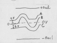
The concept first. I attach a drawing about my point of view. There will be 3 amps. Trace B will be done by a good sounding amp, like classA output stage. The other 2 is class D.
Trace A is produced by classD amp, that will take the burden from +rail to traceA. Since it will be classD, there will be good efficiency from +rail to traceA. The same is with traceC, another classD amp.
The trace from A to B or B to C will be about +/-5V, so the amp working traceB only works lightly. Can put heavy bias for B.
With no signal it will work only 10VCE or 5VCE if it is pushpull amp, for each half transistor. A and C will always 5V above or below trace B.
I think traceA and C should be 2 independent amp, so there will be 3 amp in 1 complete amp.
For easiness, I suggest for A and C we make classD with PWM controller, like TL494 or SG3525, to make everything easy. If they don't perform well, we will try other discrete design.
I'm excited about this idea. Care to make a design here about this idea? The design will be open to everyone, to critize, to modify or anything else until this idea is working fine. I believe more with more brain everything will be better.😀 Since you saw it a classH (but not analog), with classD modulating, can it be called " HD Amp"?
The concept first. I attach a drawing about my point of view. There will be 3 amps. Trace B will be done by a good sounding amp, like classA output stage. The other 2 is class D.
Trace A is produced by classD amp, that will take the burden from +rail to traceA. Since it will be classD, there will be good efficiency from +rail to traceA. The same is with traceC, another classD amp.
The trace from A to B or B to C will be about +/-5V, so the amp working traceB only works lightly. Can put heavy bias for B.
With no signal it will work only 10VCE or 5VCE if it is pushpull amp, for each half transistor. A and C will always 5V above or below trace B.
I think traceA and C should be 2 independent amp, so there will be 3 amp in 1 complete amp.
For easiness, I suggest for A and C we make classD with PWM controller, like TL494 or SG3525, to make everything easy. If they don't perform well, we will try other discrete design.
Attachments
Thanh!
Reasonable, cause it has big beta needed for transforming small current to very big current. But the delay will add. This is what I want to find out more. How bad delay in triple/quadruple darlington to sound reproduction. Add more transistor=add delay, the FB will correct the wrong signal (compared to what has happened in output). NP mentioned this as "Hall of Mirror" effect, when an amp has too many transistor stages, the FB cannot work correctly.
EVA,
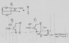
This is the sketch for making rail C (negative rail). It uses grounded type output, but in classD. Drawing A is a stiff 0-50VDC. Drawing B is when the pulses are off---the negative rail is 0V.
Drawing C is happening when the signal is -15V, so the negative rail needs tobe -20V (to maintain -5V steady offset).
The pulses are arranged so the fet will "pull" only 30V, so we have -20V compared to 0V. After the LC network, it will be smooth -20VDC.
Reasonable, cause it has big beta needed for transforming small current to very big current. But the delay will add. This is what I want to find out more. How bad delay in triple/quadruple darlington to sound reproduction. Add more transistor=add delay, the FB will correct the wrong signal (compared to what has happened in output). NP mentioned this as "Hall of Mirror" effect, when an amp has too many transistor stages, the FB cannot work correctly.
EVA,
This is the sketch for making rail C (negative rail). It uses grounded type output, but in classD. Drawing A is a stiff 0-50VDC. Drawing B is when the pulses are off---the negative rail is 0V.
Drawing C is happening when the signal is -15V, so the negative rail needs tobe -20V (to maintain -5V steady offset).
The pulses are arranged so the fet will "pull" only 30V, so we have -20V compared to 0V. After the LC network, it will be smooth -20VDC.
Attachments
The delay introduced by a single emitterfollower is a joke compared
to delays from vas or diffamp.
The delay from a cfp-outputstage is also far above the tripledarlington.
And that's what i said in an earlier post, having lowcurrentvas
enables fast transistors for vas.
to delays from vas or diffamp.
The delay from a cfp-outputstage is also far above the tripledarlington.
And that's what i said in an earlier post, having lowcurrentvas
enables fast transistors for vas.
lumanuaw :
You can make a supply rail float at audio frequencies [<20Khz sine] by using a separate transformer winding and optionally a simple common mode filter, but making something floating at SMPS frequencies [ >50Khz square wave] is not so easy, a huge common mode filter woul be required
So the circuit should be wired in such a way that power supplies use a fixed common ground, or float only for audio frequencies
Such an audio amplifier would be made of a low voltage high current linear amplifier plus two low-precision buck converters. Those converters would require a relatively high switching frequency to achieve 20Khz output, altough lower than any class D amp. The main issue with buck converters is diode recovery [it generates most of the EMI]
lumanauw said:Hi, EVA,
I'm excited about this idea. Care to make a design here about this idea? The design will be open to everyone, to critize, to modify or anything else until this idea is working fine. I believe more with more brain everything will be better.😀 Since you saw it a classH (but not analog), with classD modulating, can it be called " HD Amp"?
If I remember correctly, Labgruppen use this idea in high powered amplifiers, to get class AB quality, and class D efficiency...
sajti
Hi All,
I agree with class-A for good sound, and 'dumping/H' or running into class-AB for real power. However, more stages, ie. input/diff/mirror, VAS, all drivers plus outputs means more phase change and delay which cause distortion when the load induced back EMF leads the amplifier input. Most common Hi-Fi loudspeakers drift between -50 and +50 degrees over the audio spectrum, some are worse.
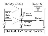
In my EW article I suggested the attached circuit for examining amplifier performance, and I see architectures being discussed here which might well show up load induced discontinuities.
An emitter follower driver stage might sound like the most innocuous of improvements, but the induced supersonic phase change which necessitates additional (propagational delaying) stabilisation components, can sometimes cause load/NFB loop induced class-A to class-B effects which are hundreds of times more deleterious than the THD figure would suggest with sine/resistor testing, and this is why simple Zen, JLH, Susan Parker or triode amplifiers can be so satisfying.
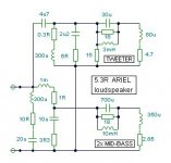
I have forwarded my approximation of the Ariel loudspeaker before, with the suggestion that amplifiers could be better tested with it as a load, instead of the always with a phase coherent 8 ohms. I will re-attach it in a second posting.
Given that most Hi-Fi amps can sport better than 0.01% THD figures, it can be surprising just how much error can be illustrated on a simulator oscilloscope with copy/pasted amps running at 10kHz in X-Y with the Ariel load versus 8 ohms. I also wrote that some amplifiers never really deserved the Hi-Fi tag that had been claimed for them.
And please don't think that I am being condescending here, for results from this test have been a been a surprise to me too !!!
Cheers ............. Graham.
I agree with class-A for good sound, and 'dumping/H' or running into class-AB for real power. However, more stages, ie. input/diff/mirror, VAS, all drivers plus outputs means more phase change and delay which cause distortion when the load induced back EMF leads the amplifier input. Most common Hi-Fi loudspeakers drift between -50 and +50 degrees over the audio spectrum, some are worse.
In my EW article I suggested the attached circuit for examining amplifier performance, and I see architectures being discussed here which might well show up load induced discontinuities.
An emitter follower driver stage might sound like the most innocuous of improvements, but the induced supersonic phase change which necessitates additional (propagational delaying) stabilisation components, can sometimes cause load/NFB loop induced class-A to class-B effects which are hundreds of times more deleterious than the THD figure would suggest with sine/resistor testing, and this is why simple Zen, JLH, Susan Parker or triode amplifiers can be so satisfying.
I have forwarded my approximation of the Ariel loudspeaker before, with the suggestion that amplifiers could be better tested with it as a load, instead of the always with a phase coherent 8 ohms. I will re-attach it in a second posting.
Given that most Hi-Fi amps can sport better than 0.01% THD figures, it can be surprising just how much error can be illustrated on a simulator oscilloscope with copy/pasted amps running at 10kHz in X-Y with the Ariel load versus 8 ohms. I also wrote that some amplifiers never really deserved the Hi-Fi tag that had been claimed for them.
And please don't think that I am being condescending here, for results from this test have been a been a surprise to me too !!!
Cheers ............. Graham.
Attachments
Hi, Sajti,
You are right. The idea is from Labgruppen (look at post #39). I just want to make the DIY version of this idea (never know what Labgruppen uses for their cct)
Hi, Mike,
Fast transistor = having big MHZ figure in databook. Will having this big MHZ figure automaticly reduce delay in real cct?
I also wonder making big bias helps to reduce delay.
Thanh!
Triple darlington can be used by using base stoppers, in the final stage, the drivers and the pre-drivers. It prevents the "negative input impedance" of the bipolars base. But, putting this base stoppers will add delay more. Its like fixing one problem, but worsen the other problem.
Hi, EVA,
You're suggesting a buck converter for +/- rail modulation? Nice idea.
Hi, GM,
Very clever test cct.
GM, how bad is it to make a many stages power amp, but with no feedback?
You are right. The idea is from Labgruppen (look at post #39). I just want to make the DIY version of this idea (never know what Labgruppen uses for their cct)
Hi, Mike,
Fast transistor = having big MHZ figure in databook. Will having this big MHZ figure automaticly reduce delay in real cct?
I also wonder making big bias helps to reduce delay.
Thanh!
Triple darlington can be used by using base stoppers, in the final stage, the drivers and the pre-drivers. It prevents the "negative input impedance" of the bipolars base. But, putting this base stoppers will add delay more. Its like fixing one problem, but worsen the other problem.
Hi, EVA,
You're suggesting a buck converter for +/- rail modulation? Nice idea.
Hi, GM,
Very clever test cct.
Problem with too many stages power amp+FB when tied to speaker. Some people always likes the sound of Non-FB power amp. Non FB do not suffer this.when the load induced back EMF leads the amplifier input.
GM, how bad is it to make a many stages power amp, but with no feedback?
Is this what I think of "FB not working correctly"?can sometimes cause load/NFB loop induced class-A to class-B effects
They all small rating amps with simple designs. Is it possible making good amp with SQ like those, but with big rating?and this is why simple Zen, JLH, Susan Parker or triode amplifiers can be so satisfying.
They are tested, giving small THD toward dummy resistive load. Maybe they behave differently if tested towards real Z-load like speaker system.Given that most Hi-Fi amps can sport better than 0.01% THD figures, it can be surprising just how much error can be illustrated on a simulator oscilloscope with copy/pasted amps running at 10kHz in X-Y with the Ariel load versus 8 ohms. I also wrote that some amplifiers never really deserved the Hi-Fi tag that had been claimed for them.
mikeb! in a your sim, I can see ac sweep from 100mhz to 10Ghz. I think you used RF-transistor . Most RF transistor has no "complemantary transistor" to it
I trying to no use darlington vas to decrease mount of stage which I must use for my amplifier
I trying to no use darlington vas to decrease mount of stage which I must use for my amplifier
Graham Maynard :
There is no need for esoteric negative-feedback fashion artifacts to explain why simple amplifier circuits 'sound' different than complex amplifier circuits when driving complex loudspeaker loads
This happens just because loudspeakers show different frequency response depending on the output impedance of the amplifier and these differences may be as wide as +-6dB when comparing simple valve-transformer circuits with complex solid state DC coupled circuits
Complex circuits show very low output impedance [in the range of miliohms] while simple exotic [or valve] circuits shor high output impedances in the range of 1 to 8 ohms. Transformers also add a couple of ohms to the output impedance of any amplifier
And obviously, a '8 ohm' loudspeaker whose actual impedance is 4 ohms at 20Hz, 20 ohms at 60Hz, 3.8 ohms at 200Hz, 7.3 ohms at 2Khz and 4.3 ohms at 10Khz does not sound the same when driven from a 3 ohms source impedance than when driven from a 30 miliohms source
Just place a 3.3 ohms power resistor in series with the output of any complex amplifier
Attached file is a quick graph of ariel's impedance...
Attachments
Hi, EVA,
Again, interesting point of view. Something related to this case.
All this time I "Think" the quality of bass has something to do with Damping factor or amplifier's output impedance. More damping factor will result in better controlled bass, but.....
Recently I read something about --bass quality is not related to damping factor--
F1 amplifier has bad damping factor, but in review, it's bass quality excell SS amp that has better damping factor.
Lots of things that we take as "right" is not perfectly "right" 😀
Hi Eva,
Quite agree with that about output impedance and speaker impedance, but similar output impedance amplifiers still sound different, and some do sound bad.
Hi lumenauw,
It is because we are trying do improve efficiency beyond class-A that we need NFB to reduce transconduction errors.
Cheers ........... Graham.
This is the resulting frequency response when driving this loudspeaker from a 3 ohm impedance source, taking as a reference the frequency response obtained with a 0.03 ohm source
Notice the bass boost and also the voice range boosted relative to the rest of frequencies
And things get even more interesting when amplifiers show different output impedances at different frequencies and different waveform amplitudes. And this allways happens in simple circuits !!!
Actually people likes simple circuits because they distort the waveform harder 😉
An externally hosted image should be here but it was not working when we last tested it.
Notice the bass boost and also the voice range boosted relative to the rest of frequencies
And things get even more interesting when amplifiers show different output impedances at different frequencies and different waveform amplitudes. And this allways happens in simple circuits !!!
Actually people likes simple circuits because they distort the waveform harder 😉
Simple cct sure cannot control as tight or as accurate as complex cct. Why people consider the sound as "nicer to hear" from simple cct amp? SET is good example if compared to pro-amps.Actually people likes simple circuits because they distort the waveform harder
But a 'controlled' bass driver allways appears to produce less 'low end' than an uncontrolled one. Lots of people like resonance tails at low frequencies. Get some power resistors and try it with different drivers/boxes
Imagine how small loudspeakers with -6dB at 50Hz benefit from the resulting bass boost when they are driven from a high impedance source [as opposed to big ones]
Most people hate equalizers, but they love how their exotic amplifiers add unexpected equalisation to their loudspeakers. Actually these people would be very happy using an equalizer or a compressor, but they fear the concept of modifying sound on purpose...
I prefer to use an equalizer and a 'linear system' instead
[By controlled I mean driven from a <0.1ohm impedance and by uncontrolled I mean driven from a >1 ohm impedance]
thanh said:mikeb! in a your sim, I can see ac sweep from 100mhz to 10Ghz. I think you used RF-transistor . Most RF transistor has no "complemantary transistor" to it
I trying to no use darlington vas to decrease mount of stage which I must use for my amplifier
Hi thanh !
No, i don't use RF-transistors, the bc546b/556b is not described as
"RF"-transistor, but is very fast with ft=300mhz.
I use acsweep up to 10ghz to be absolutely sure not to miss any pole.
As you can see, unitygain is at ~10mhz.
I think, a good replacement for darlingtonvas is cascodedvas, it
shows nearly same low distortionlevels.
lumanauw !
My understanding is, that faster transistors have less delay.
If you look into datasheet, there's a function current <-> speed.
You see that bjts have a current where they are fastest.
Smaller transistors tend to have the fastest point at lower currents,
but still several mA.
But as this is currentdependent you get problems like dynamic
phaseshift, resulting in PIM.
About "nice" sounding amps, i find the idea annyoing that flaws
from an amp are used to tune the sound, this is really not HIFI.
I have one of these (commercial), it has nice smooth sounding,
but when connected to difficult speakers (epos es12), it sounds
like having turned down ALL trebles, with the next speaker it
sounds bright, bass is boosted at ~60hz, to deep to have fun.
I hate this amp...
With my tripledarlington all these speakers have the same level
in trebles, and no longer strange bassboost/lack.
Mike
Eva said:
Most people hate equalizers, but they love how their exotic amplifiers add unexpected equalisation to their loudspeakers. Actually these people would be very happy using an equalizer or a compressor, but they fear the concept of modifying sound on purpose...
I prefer to use an equalizer and a 'linear system' instead
You made my point ! 😀
Have you ever heard uncontrolled bass on big vented boxes ? uaergh !
- Home
- Amplifiers
- Solid State
- Darlington and Triple darlington