Multibit DACs with current output have had a cult following for a long time but recently they have become very popular at diyaudio e.g. due to Miro's diy dac boards. Diyers have tried a variety of I/V stages and there are quite many subjective evaluations of these. However not that many measurements. So I decided to provide measurements of some of the popular alternatives.
DAC
The DAC used in this test is my PCM1702 board that uses PMD100 as digital filter. The board has PCM1702 L-grade chips that were used in Denon CD players. L-grade is not specified in the datasheet but all my L-grades measure about the same as K-grade. I have also J-grade chips but they measure much worse than the L-grades.
Here is the DAC board with separate I/V stage.

The DAC board caters directly for OPA1611, AD844 and AD811 (by populating appropriate I/V resistors and capacitors). Other I/V alternatives can be built as small "hat" boards that fit directly to the op amp sockets on the DAC board.
Here is a picture of the test setup.

The PSUs for the DAC board and the ADC board (ES9822PRO) are my "silent switchers" powered by power banks. DAC PSU board has 2 TPS7A39 dual regulators for +/-12V and +/-5V and a "raw" 5.5V output for the digital filter regulators on the DAC board. The connection to PC from DAC/ADC is provided by my STM32F7 USB-to-I2S board.
Lineup
Here is the I/V lineup for this test.

From left to right: OPA1611, AD844, AD811, OPA861, Folded cascode CEN clone, BJT
OPA1611
OPA1611 is often recommended for I/V duties. Here it will be used as typical op amp I/V stage in DAC datasheets so it will act as a baseline for other measurements.
BOM cost (single): 5 EUR.
AD844
AD844 is used without feedback (as in AYA dacs by Pedja Rogic). Input impedance is relatively high (50 ohms) so some stack 3 or more AD844s. Here only one is used.
BOM cost: 15 EUR.
AD811
AD811 I/V stage is based on Walt Jung's article in Audio Amateur 2/92. I used 1k stabilizing resistor. Input impedance is about 1 ohm.
BOM cost: 15 EUR.
OPA861
OPA861 is used as in the I/V stage of AYA II by Pedja Rogic.
BOM cost: 10 EUR.
Folded cascode CEN clone
This is based on the folder cascode CEN by EUVL. This is not the original folded cascode CEN but a clone.
I used 2SK209GRs as buffers. Input impedance is about 13 ohms up to 100kHz.
BOM cost: 30 EUR. This is the only one of the tested I/V stages that uses obsolete parts (2SK170/2SJ74). BOM Cost assumes matched jfets from diyaudiostore.
BJT
This is a slightly modified version of ES9018 I/V by Sérgio Santos (@smms73).
I added a similar 2SK209GR buffer as in CEN and modified some resistances for lower current consumption.
On paper (i.e. simulator) this I/V stage has very low impedance (200mOhms up to 100kHz). Parts count is high but it uses ubiquitous BJTs.
BOM cost: 10 EUR.
I/V resistor and cap is 1.5kOhms || 2.2nF on all tested I/V stages.
Measurements
I made the following measurements on each I/V stage:
Measurements are shown in subsequent posts.
DAC
The DAC used in this test is my PCM1702 board that uses PMD100 as digital filter. The board has PCM1702 L-grade chips that were used in Denon CD players. L-grade is not specified in the datasheet but all my L-grades measure about the same as K-grade. I have also J-grade chips but they measure much worse than the L-grades.
Here is the DAC board with separate I/V stage.
The DAC board caters directly for OPA1611, AD844 and AD811 (by populating appropriate I/V resistors and capacitors). Other I/V alternatives can be built as small "hat" boards that fit directly to the op amp sockets on the DAC board.
Here is a picture of the test setup.
The PSUs for the DAC board and the ADC board (ES9822PRO) are my "silent switchers" powered by power banks. DAC PSU board has 2 TPS7A39 dual regulators for +/-12V and +/-5V and a "raw" 5.5V output for the digital filter regulators on the DAC board. The connection to PC from DAC/ADC is provided by my STM32F7 USB-to-I2S board.
Lineup
Here is the I/V lineup for this test.
From left to right: OPA1611, AD844, AD811, OPA861, Folded cascode CEN clone, BJT
OPA1611
OPA1611 is often recommended for I/V duties. Here it will be used as typical op amp I/V stage in DAC datasheets so it will act as a baseline for other measurements.
BOM cost (single): 5 EUR.
AD844
AD844 is used without feedback (as in AYA dacs by Pedja Rogic). Input impedance is relatively high (50 ohms) so some stack 3 or more AD844s. Here only one is used.
BOM cost: 15 EUR.
AD811
AD811 I/V stage is based on Walt Jung's article in Audio Amateur 2/92. I used 1k stabilizing resistor. Input impedance is about 1 ohm.
BOM cost: 15 EUR.
OPA861
OPA861 is used as in the I/V stage of AYA II by Pedja Rogic.
BOM cost: 10 EUR.
Folded cascode CEN clone
This is based on the folder cascode CEN by EUVL. This is not the original folded cascode CEN but a clone.
I used 2SK209GRs as buffers. Input impedance is about 13 ohms up to 100kHz.
BOM cost: 30 EUR. This is the only one of the tested I/V stages that uses obsolete parts (2SK170/2SJ74). BOM Cost assumes matched jfets from diyaudiostore.
BJT
This is a slightly modified version of ES9018 I/V by Sérgio Santos (@smms73).
I added a similar 2SK209GR buffer as in CEN and modified some resistances for lower current consumption.
On paper (i.e. simulator) this I/V stage has very low impedance (200mOhms up to 100kHz). Parts count is high but it uses ubiquitous BJTs.
BOM cost: 10 EUR.
I/V resistor and cap is 1.5kOhms || 2.2nF on all tested I/V stages.
Measurements
I made the following measurements on each I/V stage:
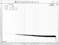
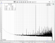
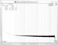
- THD(+N) at 0dBFS
- Noise (DAC playing -180dBFS)
- THD vs. level sweep at 997Hz.
Measurements are shown in subsequent posts.
Last edited:

OPA1611
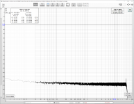
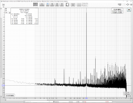
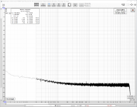
THD(+N) at 0dBFS is slightly higher than datasheet specs for K-grade. For some reason the other channel had about 3dB better THD(+N) and swapping the op amps did not make any difference. Noise is very low.
THD(+N) at 0dBFS is slightly higher than datasheet specs for K-grade. For some reason the other channel had about 3dB better THD(+N) and swapping the op amps did not make any difference. Noise is very low.
Attachments
AD844
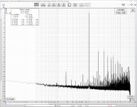
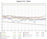
THD(+N) at 0dBFS is much higher than in OPA1611. In addition to 2nd and 3rd also 4th-6th HDs are elevated. Noise is only slightly higher than in OPA1611. THD sweep shows a clear increase of HD above -6dBFS.
THD(+N) at 0dBFS is much higher than in OPA1611. In addition to 2nd and 3rd also 4th-6th HDs are elevated. Noise is only slightly higher than in OPA1611. THD sweep shows a clear increase of HD above -6dBFS.
Attachments
OPA861
THD(+N) is high at 0dBFS. Noise is also high. THD sweeps shows that 2nd HD rises already at -25dBFS. Also 3rd rises clearly above -8dBFS. All in all not surprising as I had already seen similar results in my AYA II DAC.
THD(+N) is high at 0dBFS. Noise is also high. THD sweeps shows that 2nd HD rises already at -25dBFS. Also 3rd rises clearly above -8dBFS. All in all not surprising as I had already seen similar results in my AYA II DAC.
Attachments


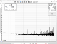
Folded cascode CEN clone
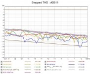
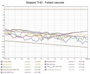
THD(+N) at 0dBFS is about 10dB worse than in e.g. AD811. Noise is about 3dB higher than in e.g. OPA1611. THD sweep shows a decreasing trend up to about -8dBFS at which point 2nd and 3rd start to rise.
Even though I had a relative well matched quartet of 2KS170/2SJ74 (idss within 0.2mA) the other channel (not tested here) had about 10dB worse THD(+N) at 0dBFS.
Attachments

Last edited by a moderator:
BJT
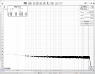
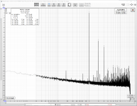
THD(+N) is lowest of the lot. It is even better than datasheet specs. Noise is also low. THD sweep shows nice decreasing trend all the way up to 0dBFS.
One thing to note is that no matching of BJTs was required. I only used a matched pair of buffer jfets.
THD(+N) is lowest of the lot. It is even better than datasheet specs. Noise is also low. THD sweep shows nice decreasing trend all the way up to 0dBFS.
One thing to note is that no matching of BJTs was required. I only used a matched pair of buffer jfets.
Attachments

Conclusion
I made brief listening evaluation of each I/V stage with both headphones and speakers. However proper AxB listening test was not possible due to the time needed for switching I/V stages. None of the I/V stages sounded exceptionally good or bad. Even the OPA861 sounded quite ok as the high distortion is mostly benign 2nd and 3rd. With the exception to OPA861 and AD844 I would probably find it difficult to confidently identify each I/V stage in a blind test.
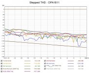
Regarding the measurements one thing visible in THD sweeps is that 3rd to 5th harmonics are very similar below -14dBFS in each I/V stage. So below -14dBFS the tested DAC chip seems to be the limitation for 3rd to 5th HD. Above -14dBFS the I/V stage THD starts to dominate. I would guess that the I/V stages with lowest THD in this test are near the limit of PCM1702.
Based on the measurements the winner in this test is the discrete I/V stage by @smms73. What makes it even more remarkable is that it is a "zero-feedback" design with lower THD(+N) than high-specification op amp with feedback. Kudos to @smms73!
I made brief listening evaluation of each I/V stage with both headphones and speakers. However proper AxB listening test was not possible due to the time needed for switching I/V stages. None of the I/V stages sounded exceptionally good or bad. Even the OPA861 sounded quite ok as the high distortion is mostly benign 2nd and 3rd. With the exception to OPA861 and AD844 I would probably find it difficult to confidently identify each I/V stage in a blind test.
Regarding the measurements one thing visible in THD sweeps is that 3rd to 5th harmonics are very similar below -14dBFS in each I/V stage. So below -14dBFS the tested DAC chip seems to be the limitation for 3rd to 5th HD. Above -14dBFS the I/V stage THD starts to dominate. I would guess that the I/V stages with lowest THD in this test are near the limit of PCM1702.
Based on the measurements the winner in this test is the discrete I/V stage by @smms73. What makes it even more remarkable is that it is a "zero-feedback" design with lower THD(+N) than high-specification op amp with feedback. Kudos to @smms73!
Folded cascode CEN
This is based on the folder cascode CEN by EUVL.
I used 2SK209GRs as buffers. Input impedance is about 13 ohms up to 100kHz.
BOM cost: 30 EUR. This is the only one of the tested I/V stages that uses obsolete parts (2SK170/2SJ74). BOM Cost assumes matched jfets from diyaudiostore.
While I am flattered to have you taking all the trouble to clone my Folded Cascode CEN IV, I guess it is not unfair to call this a clone.
And I would appreciate you do name it as such -- a FC CEN IV clone.
I am not sure whether or how you have received a BoM for the through hole version of the original FC CEN IV, certainly not from us.
On top of that, you are using all SMD components for the other active devices, which are over-stressed with the 8mA bias current of the frontend JFETs.
In addition, the 2SK209GR is known to be 10dB worse in THD than the 2SK170BL, unless you have 2 in parallel.
https://www.diyaudio.com/community/...minimalistic-iv-converter.195483/post-3394706
And it has also been made known to the FC CEN builders that running at 12V rails will compromise performance.
BTW the FC CEN is also a zero feedback circuit based on current conveyor.
Having said that, I am happy to take -89dB H2 and -103dB H3 any day.
I run my own balanced, and I know how good my own matching is (not just the JFETs), so I easily get -20dN H2 cancellation over many years.
If one just wants to chase after THD figures at 1kHz, look no further than high loop gain opamp IV.
As to subjective evaluations, I always leave it to others to judge, as it is subjective.
Last but not least, all my respect to Sergio (smms73) who certainly knows how to design circuits.
I still treasure the great time we had 10 years ago discussing circuit variants of the original SEN IV :
https://www.diyaudio.com/community/...minimalistic-iv-converter.195483/post-3394706
Did he not mention 0.00009% THD with 2sk170 ?
Best regards,
Patrick
Last edited:
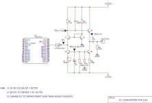
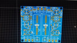
Hi! hoping not to be of topic, I wanted to share this simple circuit that I found in my old notes. I have already made the PCB and I must say that I am satisfied.
I used bc550c, but in a few days I will use 2sc1815bl. Can any of you simulate this? If valid I can provide the Gerber file.
I used bc550c, but in a few days I will use 2sc1815bl. Can any of you simulate this? If valid I can provide the Gerber file.
Attachments
I can note that use of PMD100 in stand alone mode is by factory preset 8X oversampling?
.
And yes, Sergio Santos IV circuits are well behaving in the sims too. maybe the best... 🙂 Very flexible and adoptable. Even for tube, after IV amplifying, stages with negative bias already "at the hands"... Excellent that someone actually build such an IV, try the sound and measure.
.
And yes, Sergio Santos IV circuits are well behaving in the sims too. maybe the best... 🙂 Very flexible and adoptable. Even for tube, after IV amplifying, stages with negative bias already "at the hands"... Excellent that someone actually build such an IV, try the sound and measure.
Erm, I think you mean FET, not BJT. BJT means NPN or PNP with minority carriers doing the work. FETs are majority carrier. https://en.wikipedia.org/wiki/Bipolar_junction_transistorOne thing to note is that no matching of BJTs was required. I only used a matched pair of buffer jfets.
Erm. Maybe you should look at the schematic. How many FETs do you see?Erm, I think you mean FET, not BJT.
"One thing to note is that no matching of BJTs was required. I only used a matched pair of buffer jfets."
Source of his confusion?
Source of his confusion?

- Home
- Source & Line
- Digital Line Level
- DAC I/V measurements