I wonder what's the noise of a bc transistor at 4.5...7 ma...for some reason i think that the noise will be much higher than the distortion figures...
Rb of the BC5xx is somewhere between 160 (Onsemi) and 800.
The ES9018 output resistance is 780, so you get a loss of 3db SNR in the worst case?
Rb of the BC337/327 is probably below 40.
The ES9018 output resistance is 780, so you get a loss of 3db SNR in the worst case?
Rb of the BC337/327 is probably below 40.
Is that all with these complex circuits running at high currents, the noise generated by one transistor rbb?
Keantoken is right, the input transistors are not very important for total noise, the ones that matter are the ones in the current sources and the emitter resistance of those bjt, there are some modern transistors that have rbb of less than 2 ohms (0.2 nV/√Hz), and those are perfect for the current sources
There are so many circuits posted, it bears some investigation. But the Smedegard circuit could use a capacitor across the bias transistor.
If you really want to get esoteric you can use an opamp to make a virtual resistance which has lower noise than a physical resistor.
BTW, getting Rb right is actually crucial for having the correct RF behavior of BJT models in simulation. Transistors with high Rb will tend to be unstable in feedback loops. So someone needs to measure the Rb of currently available transistors. There are Rb measurements out there, but usually from knuckleheads who didn't bother to write down who made their transistor. Different manufacturers usually have different Rb.
Last edited:
The Art of Electronics 3rd Edition | by Horowitz and Hill
The book has a chapter about noise with lots of measurement of the base spreading resistence (rbb), with the indication of manufacturers.
Kentoken I have instability with bc327/337 in the complementary compound pair and not with bc847/857 , do You know why this happens.?
The book has a chapter about noise with lots of measurement of the base spreading resistence (rbb), with the indication of manufacturers.
Kentoken I have instability with bc327/337 in the complementary compound pair and not with bc847/857 , do You know why this happens.?
Is that all with these complex circuits running at high currents, the noise generated by one transistor rbb?
High current (Ic) is important if you want to reap the benefits of a transistor with low base spreading resistance (rbb), for transistors with high rbb high Ic is not important.
The Art of Electronics 3rd Edition | by Horowitz and Hill
The book has a chapter about noise with lots of measurement of the base spreading resistence (rbb), with the indication of manufacturers.
I was going to mention that as well. Actually, AOE is most expensive book I ever bought, but also the most useful on almost a daily basis. Quality and facts still are never free even with the internet.
Jan
Do your BC5xx models have a reasonable value for Rb? As Onsemi has acquired Fairchild and replaced their TO92 line with Fairchild factory parts, Rb is no longer the typical low Onsemi value. Try 596R (Phillips) and see what that does.
I wish I had that book but I don't and maybe never will.
I wish I had that book but I don't and maybe never will.
Please disregard the off-topic direction of this post, it's only intended to throw a bit of "light" on a highly disregarded subject of the audio industry as most of the audiophile guys i know are buying new and newer audio equipment each year feeling a great discomfort in most of the assumed quotes of the audio industry, like "vanishingly low distortion", or "noiseless reproduction"... and i couldn't make any of them throw in the bin their valve amplifiers, tape recorders or very high THD Harman Kardon amplifiers...
I had all three editions of AOE, but my questions was if the noise would dominate the bottom thd line...some of the mentioned circuits are quite complex , they have very high gain, common base circuits are known for very low PSRR, their CCS have to be very high quality , the real power supplies aren't so low noise as we usually dream to be and they also run at high currents which i think is going to enhance other type of noises and non linear distortions due to thermal behavior.
I might be wrong about these particular circuits , i'm not the expert here...I think that this types of I/V circuits need very careful PCB and power supply design .
Personally , i deeply discourage people in looking for very low THD as THD is the only distortion factor that can hide all the other problems of a circuit.I'd prefer a higher, even audible THD over a higher noise or non-linear circuit.
This is not only my take-on on audio, is actually the winner take-on in the whole audio industry for a long time and it will always be because THD means "total HARMONIC distortion" and we prefer harmonic distortions to nonlinear ones or nonqualified noise or perfectly reproduced but low quality music 🙂
In the end is not the aim of this topic and i do understand that, but i can hardly see the utility of ultra low distortion circuits.
I've read the Small signal amplifiers book of D.Self a few years ago, i'm still reading all of them...and i thought for a while that low distortion is really what I'm looking for, i even tried most of its analog circuits and i still remember the fact that he was deeply against the use of OP275 as it was very high noise and very high distortion compared with me5534 and i don't doubt it, not at all, but i did use that op275 in a very high quality player after the i/v circuit and i liked the sound of it way more than the sound of ne5532 , most probably because its THD was a pleasant one...while all the other downsides were simply masked by the "so much hated" THD.
When a musician is playing, his art is mainly hidden in harmonic play, in enriching the sound of its presentation and if you listen the same melodic base of a song on multiple instruments, you'll find out that you like the most the version with the most harmonic content...
I've worked once on a circuit having the ess9018 in it and the real problem was to make the ESL transducer driven by the whole circuit sound good and for that we needed to raise the THD in the ballpark of 0.2...1% THD, from its basic 0.002% final amplifier THD driven by a 0.0001% THD dac , so it was pretty hilarious to use a 30 dollar chip, and xmos circuit and about 10 very low THD and vanishingly now noise op-amps to listen to a fabricated 0.2..1%THD, just to hide the distortions generated by the transducer itself...The final result was a very good sounding system though...
Do your BC5xx models have a reasonable value for Rb? As Onsemi has acquired Fairchild and replaced their TO92 line with Fairchild factory parts, Rb is no longer the typical low Onsemi value. Try 596R (Phillips) and see what that does.
I used the model that came in Ltspice and they have RB value of 10 😱
I then used cordell bc550c/560c model that has a RB of 170 and the HF instability returned, so you were also right in this one
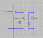
I think the best opinion is to use a capacitor for stability (c4)
Attachments
I wish I had that book but I don't and maybe never will.
The lower price that I found is in Amazon UK for 40GBP used
Amazon.co.uk: Buying Choices: The Art of Electronics - third Edition
it's worth every penny!The lower price that I found is in Amazon UK for 40GBP used
Amazon.co.uk: Buying Choices: The Art of Electronics - third Edition
i found a similar topic:BTW guys, have you ever seen this ultimate I/V converter??
Jan
https://www.diyaudio.com/forums/dig...dac-ad1853-discrete-output-6.html#post4018512
Last edited:
To remove the noise of Q9, C2 needs to be much larger. The transresistance of Q9 is 0.026/Ic, so if it is at 3mA, the capacitance needed for a 4Hz corner frequency would be 4.6mF. It's not so important for the BC337 though with such low Rb.
It is not advisable to put a 4.7mF capacitor in this position, because when the power is turned on the input voltage would be -0.6v for 2 seconds which could damage the DAC, anyway the contribution to the total noise of this transistor is negligible. C2 is only there to decrease the impedance at high frequencies.
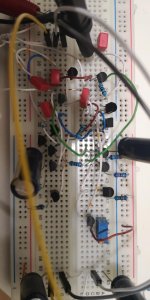
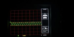
This week I tested the circuit with the input (complementary compound pair), and I am quite happy with the result, the circuit behaved exactly as expected by the ltspice, the input impedance is less than 0.5ohms to 1Mhz (photo2) as provided in ltspice, and should be around 25mohms at 20khz, in photo 2 it is possible to see the voltage at the input with a signal of 4mA pp of 1Mhz.
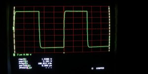
The third photo is of the output with a square signal of 100Khz, very clean with no signs of over-shoot or riging.
Thanks to Jan.didden for showing me the circuit of Michael Smedegaard, it was very inspiring.
The third photo is of the output with a square signal of 100Khz, very clean with no signs of over-shoot or riging.
Thanks to Jan.didden for showing me the circuit of Michael Smedegaard, it was very inspiring.
Attachments
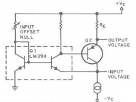
Another inspiration (maybe): my own first steps in this area:
Simple, high-quality I/V converter | Linear Audio NL
Note that the label 'input voltage' in fig 2 should really be 'input current' as this is obviously an I/V converter...
Also one page is out of order, sorry about that.
(I must also admit that some of my ideas expressed are now changed, sometimes a lot. But the article hopefully is still enjoyable).
Jan
Attachments
Last edited:
i have a few lm394 and i could pair it with 2sa1038 (ultra low noise high hfe transistor), 2sa992(low noise, high hfe too) or ztx951, much lower hfe...What would be the best combination?Another inspiration (maybe): my own first steps in this area:
Simple, high-quality I/V converter | Linear Audio NL
(I must also admit that some of my ideas expressed are now changed, sometimes a lot. But the article hopefully is still enjoyable).
Jan
would this work well for low iout dac, less than 1ma output current?
I would use a low noise jfet for ccs , but i'm not sure if high transconductance j-fet are stable enough with high current modulation.What would you recommend as current source, a cascode, simpler?
I am not interested in ultra low thd, everything that i usually design is in the ballpark of maximum 90db of LtSpice, which is most probably 75 db in the real life but i don't really want anything higher than that.I am only concerned with stability of operation , low noise and high bandwidth.
Last edited:
i have a few lm394 and i could pair it with 2sa1038 (ultra low noise high hfe transistor), 2sa992(low noise, high hfe too) or ztx951, much lower hfe...What would be the best combination?
would this work well for low iout dac, less than 1ma output current?
I would use a low noise jfet for ccs , but i'm not sure if high transconductance j-fet are stable enough with high current modulation.What would you recommend as current source, a cascode, simpler?
Obviously both high Hfe and low noise would be beneficial.
For the current source it is important that it doesn't change too much with temperature. As the offset adjustment is open loop with the trimmer, CCS changes will lead to a change in offset voltage at the current input which you don't want to get too high. For my case that should be less than 10mV for best results, but modern DACs often allow more offset without degradation in linearity, check the data sheet.
Note that the CCS does not see any current modulation (the input current is into the emitter, the CCS is, as its name says, constant current), and also very, very little voltage modulation (the emitter doesn't change more than a few mV due to input current).
Jan
- Home
- Source & Line
- Digital Source
- dac I/V convertion with very low distortion