Very nice but in the same time very impractical because the tube are exposed and can be accidentally broken and on top of the DAC box you can't put anything. For example the power amplifier is recommended to be on top for better cooling.
My guy, that is what audio racks are for! If I was concerned about practicality, I wouldn't build with tubes at all 🙂


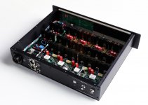
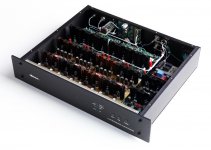
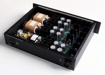
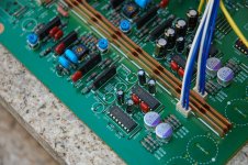
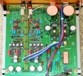
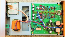
pair of PCM63 in parallel per channel, NOS design. I/V conversion done by Sowter 1465 SUTs, coupled to a E182CC / 7044 / 5687 tube gain stage, battery biased, and loaded by Sowter 9705 line output transformers. B+ supply is Maida regulated,
Nice build. How does it sound?
I sourced the parts and built the boards and Les Bordeleon did the chassis and assembly
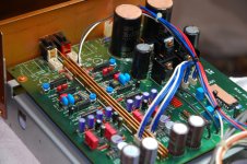
2 chassis - dac and power supply
AC soft start
8 x 1704 K grade multiplexed for 192/24 fully balanced
3 x 100w R core
3 x diy audio CRC power supply boards with IR hexfet - Quasimodo CRC snubbed
200,000uf filter caps
10 Jung super regulators as pre regulators
10 Borbely super Shunt regulators 389/109 jfets and 2013/313 fets
Borbely jfet/ Fet 80 ma bias current Class A single stage IV/output buffer 389/109 and 2013/313
Blackgate electrolytics
Relcap teflon and polystyrene caps
Texas Components TX 2575 signal path resistors
Silver wire
Attachments

Last edited:
Nice build. How does it sound?
It sounds great, extremely lifelike, airy and spacious with tactile bass. It's the best digital source component I've owned, head and shoulders above my first PCM56 design as well as my Audial S5 NOS DAC.
Please, can I ask you about your design decisions in this fine build?
1. PCM63 in parallel per channel Q: why x2 PCM63? Twice the cost for what? Maybe 3dB SNR? Seems redundant?
2. I/V conversion done by Sowter 1465 SUT. Q: why use a trannie for IV?
3. Battery biased Q: are the batteries rechargeable?
4. B+ supply is Maida regulated, one per channel. Q: why SS B+.?? How does SS sound? They are pricey – could one do both channels?
5. Heaters are also DC regulated. Q: Coleman regs?
Thanks 🙂
1. I picked up four of these chips together about a year ago, as such I wanted to use all four in a single design. I considered a balanced design, but decided to go parallel. Half the I/V secondary resistance is needed for a given output voltage with two chips in parallel, which will improve performance. There is also a theoretical averaging/error correction of the R2R resistors with two chips in parallel. Also just subjective testimonials of running two chips in parallel, I wanted to try. Cost was not a concern for this project.
2. Sowter SUT I/V was recommended to me by a fellow DIYer, I used it in a previous build and was happy with the result. Relative to other passive I/V (i.e., resistor), it provides voltage gain, allows for a lower reflected impedance to the DAC output, and provides low pass filtering.
3. In class A1, tube grids will draw no current, the batteries are not drained, they need to be changed at the shelf life of the battery. For AA, that is ten years.
4. The regulators I used are a friend's design, they are very high performing, I've used them in multiple designs, they are not expensive. I used two regulators for better decoupling between L and R channels
5. Not Coleman regs, these are not directly-heated triodes. DC heater regulator is my design, purpose is to avoid coupling of 60Hz noise into the output stage.
OT: Why DACs are discussed on this Digital Line Level forum, shouldn't they rather belong to Digital Source?
What if you have ADC->DSP->DAC ? (Line level in and line level out) Then the dac part has to be a separate forum?
All Line Level I would assume. Whatever. One can make it as complicated as one likes.
This thread is a "DAC gallery" listed under Digital Line Level and that seems to cover it.
This thread is a "DAC gallery" listed under Digital Line Level and that seems to cover it.
Member
Joined 2018


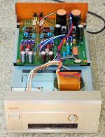
TEAC D-700:
My last 2R2 DAC purchase, with 4x AD1862N-Z. I've upgraded the diodes to BYV27-50, several capacitors are renewed and all the jumper wires are changed to Neotech UP- OCC copper wires.
I hope you will enjoy the pics.
My last 2R2 DAC purchase, with 4x AD1862N-Z. I've upgraded the diodes to BYV27-50, several capacitors are renewed and all the jumper wires are changed to Neotech UP- OCC copper wires.
I hope you will enjoy the pics.
Attachments
Beautiful.
I've always wanted one!
It cost about 700 bucks in 1992. 😳
https://audio-database.com/TEAC-ESOTERIC/etc/d-700.html
Very orderly interior.
I would have expected only the transformer/ps a little more "robust", as far as we can say only looking it, but I'm so set in power supply.
Good job inside. 👍
I've always wanted one!
It cost about 700 bucks in 1992. 😳
https://audio-database.com/TEAC-ESOTERIC/etc/d-700.html
Very orderly interior.
I would have expected only the transformer/ps a little more "robust", as far as we can say only looking it, but I'm so set in power supply.
Good job inside. 👍
I know the post I quote is pretty old. I spotted it yesterday. It looks like these boards are still available. Judging from the number of op amps on board the DAC is working in voltage output mode?Recent DAC project
Here’s a recent project I built based on the ESS ES9038Q2M DAC chip on a Chinese module acquired through Ebay. This is a stand alone DAC in its simplest form with just one optical and one coaxial digital input and the analog output.
I have made a few minor mods to the module which include:
1) removed the on board connectors for the input, outputs, and power so I could use panel mount connectors instead. Left the optical input intact.
2) added the screw terminal for DC power connection
3) removed the volume control connector and replaced it with a multi-turn pot for level matching
4) replaced the output coupling capacitors with Elna Silmic series audio caps.
5) replaced the NJM5532 with an LT1057 (done after the photos)
The power supply is just a simple +/- 15 VDC design built with 78/79 series regulators. The case was built from industrial scrap and aluminum panels recovered from an old Mac computer case.
PCM filter selection is done manually with jumpers. The ES9038Q2M has 7 available filter types, all of which don’t start to roll off until 20 KHz or higher. I tried them all and couldn’t hear any difference, so I saw no need for a more advanced selection method. I simply chose the linear phase slow roll off filter because it has the cleanest impulse response as indicated in the data sheet graphs.
I am very pleased with the sound, as it is clean, detailed and smooth. Separation and imaging are also very good. I’ve been listening for about 8 months to an identical module I put in another system, so I have had the chance to listen to a wide variety of recordings all of which sound great.
I don’t have the equipment to make any distortion measurements so I can’t provide any info in this area. Thanks.
But then it is probably not difficult to cut some traces and take the output from current output. Does anybody have any experience with doing it with these boards?
Yes, this board works in voltage mode. I have several of them in my systems and I'm happy with their performance, pretty much as is.
There are many threads about this one and other ES9038Q2M boards.
Some are hundreds of pages long and you can find every tweak under the sun that's been done, audible or not.
Good luck.
There are many threads about this one and other ES9038Q2M boards.
Some are hundreds of pages long and you can find every tweak under the sun that's been done, audible or not.
Good luck.
While trying to avoid getting too off-topic in this thread, ES9038Q2M is not the dac chip in the sort of intermediate product range that is most favored in professional audio applications. The more or less intermediate level chip that has had the most market success in for professional use is probably more like AK4493. If interested in a dac for music reproduction, that might be a better place of focus attention. OTOH, ESS dacs tend to excel at standard 'figure-of-merit' measurements. For that reason ES9038Q2M may be a good choice pretty decent measurement dacs. If anyone would like more discussion on that topic, a better place might be the ES9038Q2M Board thread.
- Home
- Source & Line
- Digital Line Level
- DAC gallery