Here the final schematic
Got my LL 1684 but I am not sure I understand ground connections on this schematic. 😕
Got my LL 1684 but I am not sure I understand ground connections on this schematic. 😕
Where is the problem ?
Balanced output need center tap to ground
Un-balanced output need lateral tap to ground
Where is the problem ?
Balanced output need center tap to ground
Un-balanced output need lateral tap to ground
So there is a switch ?
Hello Andrea,Here the 58a standby for you.
I tried this version , but the display remain black ( no display) and remote
control has no effect ?
I came back to the precedent version and all is ok.
Br
Jacky
Hello Andrea,
I tried this version , but the display remain black ( no display) and remote
control has no effect ?
I came back to the precedent version and all is ok.
Br
Jacky
This version is not for all, this is the standby version to use only if there is a separated transformer for controller.
This version is not for all, this is the standby version to use only if there is a separated transformer for controller.
Sorry Andrea , i should to pay attention !
Br
Jacky
Where is the problem ?
Balanced output need center tap to ground
Un-balanced output need lateral tap to ground
How will a 22 uf Bipolar Capacitor ( like nichicon muse ) work between gnd in and gnd out. High frequences ( noise) will not pass the Capacitor.
How will a 22 uf Bipolar Capacitor ( like nichicon muse ) work between gnd in and gnd out. High frequences ( noise) will not pass the Capacitor.
Did not work at all almost no signal. 🙄
Did not work at all almost no signal. 🙄
well big mistake . My power amps was in se mode at input. But the sound . I really do not like it. 🙁 Have to change the 2x15 uf. RFX Mundorf and 2x 6,8 nf. Silver Mica to Black Gate.
I am going to buy the chip quik de solder kit SMD1 or SMD1NL to help with some of the modifications/fixes.
Should I buy the standard or the lead-free version of the kit?
Chip quik uses a low melt solder which combines with the solder on the chip and reduces its melting point. So I need to know whether the DAC board has been soldered lead-free or not. Can anyone help?
Should I buy the standard or the lead-free version of the kit?
Chip quik uses a low melt solder which combines with the solder on the chip and reduces its melting point. So I need to know whether the DAC board has been soldered lead-free or not. Can anyone help?
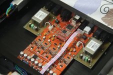
I use LL 1684 for output off my dac now , but I do not like the sound at all. Distortion and very hard midrange and treble. Maybee I should change the Capacitors for that circuit ? I use 2x 15 Uf Mundorf RXF and 2 x 6,8 nf Silver Mica for each channel.
Hi Quanghao,
Two questions:
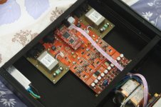
1) What is the function of the pink wire that connects R44 to R3 ( post 2073 )? In my DAC the two resistors are not mounted.
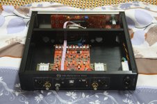
2) With the DAC/1684 you have tried to keep floating the two secondary of the trasformer and connect to chassis pin 1 of the XLR ( balanced output )?
The DAC with opamp sound wonderful.
Two questions:
1) What is the function of the pink wire that connects R44 to R3 ( post 2073 )? In my DAC the two resistors are not mounted.
2) With the DAC/1684 you have tried to keep floating the two secondary of the trasformer and connect to chassis pin 1 of the XLR ( balanced output )?
The DAC with opamp sound wonderful.
Hi Quanghao / Andrea,
Are three any unused input / output pins on the PIC that I can use? I would like to implement trigger in/out functions. Would need to program the PIC obviously and I guess build some sort of daughter board to piggy back onto the PIC socket. I can then completely replace my preamp!
Are three any unused input / output pins on the PIC that I can use? I would like to implement trigger in/out functions. Would need to program the PIC obviously and I guess build some sort of daughter board to piggy back onto the PIC socket. I can then completely replace my preamp!
- Status
- Not open for further replies.
- Home
- More Vendors...
- Quanghao Audio Design
- DAC-END R (ES9018) full assembled board