Mundorf RXF ?
Try simple 10uF 6.3V OS-CON Sanyo or good MKP like Z-Cap red
Would 47 uf be ok or is that to much ?
Would 47 uf be ok or is that to much ?
ok, no problem
Hi Quanghao / Andrea,
Are three any unused input / output pins on the PIC that I can use? I would like to implement trigger in/out functions. Would need to program the PIC obviously and I guess build some sort of daughter board to piggy back onto the PIC socket. I can then completely replace my preamp!
Do you need to use these pins connected to relay ?
Do you need to use these pins connected to relay ?
I probably do. I think the way the DAC with standby works now is that on receiving the power on signal from the remote, the relay turns on AC to the transformers, thereby powering up the DAC. Hopefully, the reverse will happen with your new standby firmware - I can't test it yet as my programmer has not arrived as yet. I would like the possibility of two things...
Firstly (and less important), the ability to turn ON the DAC using an external 12V trigger. I presume this will require a spare input into the PIC. In other words, when a signal is detected in the spare input, the relay should turn on the DAC as if the power button on the remote has been pressed.
Secondly, and much more important, the ability to provide a 12V trigger signal for my power amps. I thought of hanging a 12V transformer and building up a circuit for the 12V trigger. This would mean that the 12V trigger will start up my amps as soon as the DAC powers up, and the soft start on the amps will ensure that the power amps will turn on AFTER the DAC. However, when power is removed from the DAC, the amps will power off immediately. I would like to do it in such a way that the amps will turn on after the DAC and turn off before the DAC. I think this would require a spare output on the PIC to turn on/off another relay for the 12V - when turning on, the relay will turn on first then the 12V output, with the reverse order when turning off. A side effect will be to have another power source (5V ?) for a cubox or something similar to act as a streamer.
In my simple thinking, I think the easiest way to implement this would be to have a daughter board which would plug into the current PIC socket, and the PIC to plug into the daughterboard. All the current used pins would be transferred directly to the controller board whilst the 2 extra pins required can come out as a header and subsequently plugged into another board with the necessary relays / AC to DC converter etc.
I hope this all makes sense!
ok, no problem
I use 47 uf . Black Gate for speakers, 330 nf; Mundorf ZN and 22 nf. Wima FKP.
Its just fantastic. 🙂
Never been near the sound I have now.
I use 47 uf . Black Gate for speakers
What's a Black Gate for speaker?
I think of them as standard, N, NX, etc.
Randy
TarnishedEars ,
look only post #1586
So this maybe my imagination, but I added the 100nf caps to the 1.2 and 3.3v regulators, and I think it sounds better.
I used 0612 caps, with the metal parts on the long side instead of the short side, they are low impedance, and it took a little work to get them in.
For me, I needed tweezers and a good magnifying glass to do it.
Ordered some 1uf caps so I can finish this mod.
What's a Black Gate for speaker?
I think of them as standard, N, NX, etc.
Randy
The Blue 50 V AC. They are bigger then the rest. I have 2 more if you want. It is not possible to buy them anymore.
Yesterday I thought my system was bad sounding again . To much treble and midrange and no bass. I ordered 10 kohm Amtrans to bring down input impedance off my Holton amps.
If output impedance is 200 ohm the 40 kohm impedance off the Amps are to high. Without the transformers and 100 ohm I/V resistors I had much more bass.
Hi Quanghao,
Two questions:
1) What is the function of the pink wire that connects R44 to R3 ( post 2073 )? In my DAC the two resistors are not mounted.
2) With the DAC/1684 you have tried to keep floating the two secondary of the trasformer and connect to chassis pin 1 of the XLR ( balanced output )?
The DAC with opamp sound wonderful.
That is R set current for shun, no need more it!
yes, the out put transformer you can try do it,a and wait me have pcb for it!
thanks
thanks
Load for LL1684
In the data sheet , recommanded load is : 10 k // 1k + 3 nF, for best square signal response.
In my system, i don't have this load and the 20 hz level is the same than 1 KHz .
Compared to my FDS366T, the sound is more dynamic , scene is wider and more background details are present.
Now, I must adjust levels and make resonnance corrections between three ways of my active system to make definive conclusions.
Br
Jacky
What is best impedance load for 1684 ?
In the data sheet , recommanded load is : 10 k // 1k + 3 nF, for best square signal response.
In my system, i don't have this load and the 20 hz level is the same than 1 KHz .
Compared to my FDS366T, the sound is more dynamic , scene is wider and more background details are present.
Now, I must adjust levels and make resonnance corrections between three ways of my active system to make definive conclusions.
Br
Jacky
Thank you ! 🙂
Do you use a pre between Dac and Power amp ? I do not . I think it is more dynamic in midrange and treble but bass is a problem. I think lowering the input impedance off my power amps will help. Also I just got another schematic from Quanghao. I will try that. 🙂
Thank you ! 🙂
Do you use a pre between Dac and Power amp ? I do not . I think it is more dynamic in midrange and treble but bass is a problem. I think lowering the input impedance off my power amps will help. Also I just got another schematic from Quanghao. I will try that. 🙂
I use Andrea's schematic , unbalanced outputs.
In this case , best result is when output pin 4 of LL1674 is connected to DAC ground.
The efficiency of my system is 105 db/1w/1m For 3W at the output amplifier , the output DAC volume level is -21 dB , so i don't use preamplifier between DAC and power amplifier.
Br
Jacky
Ok you have complete different system . My loudspeakers is 89 db and Qts is around 0,38 . So maybee I will need a pre.
I use Andrea's schematic , unbalanced outputs.
In this case , best result is when output pin 4 of LL1674 is connected to DAC ground.
Pin 4 to ground? that's weird for unbalanced.
My LL1684s are configured like this.
To solve a grounding issue I had to connect DAC/PCB ground to pin 2 (RCA ground).
I have confused pin 4 and 5 for gnd. Now the sound is completely changed. The first report when I thought it was good was 3 o ;clock in the morning playing very low. 😱
I have confused pin 4 and 5 for gnd. Now the sound is completely changed. The first report when I thought it was good was 3 o ;clock in the morning playing very low. 😱
Using LL1684 remember to remove the I/V jump
Pin 4 to ground? that's weird for unbalanced.
My LL1684s are configured like this.
To solve a grounding issue I had to connect DAC/PCB ground to pin 2 (RCA ground).
Yes , like that !
Attachments
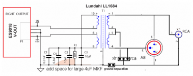
Your secondaries are connected differently, I don't know the effect of that.
Mine are connected like the serial-serial connection in the LL1684 datasheet.
Mine are connected like the serial-serial connection in the LL1684 datasheet.
Using LL1684 remember to remove the I/V jump
Off course I am not that confused 🙂
- Status
- Not open for further replies.
- Home
- More Vendors...
- Quanghao Audio Design
- DAC-END R (ES9018) full assembled board