Same problem 48k limit on coax, 96k on toslink. Is toslink affected by the fake comparator ? Have we a precise circuit diagram about this part of the dac board (coax,toslink,aes-ebu)?
Toslink is fine, it's not affected by comparator IC.
192KHz on Toslink is very much determined by source and cable quality. Toslink was originally designed up to 96KHz only, though in some cases it manages to play 192KHz.
192KHz on Toslink is very much determined by source and cable quality. Toslink was originally designed up to 96KHz only, though in some cases it manages to play 192KHz.
Last edited:
Toslink is fine, it's not affected by comparator IC.
192KHz on Toslink is very much determined by source quality. Toslink was originally designed up to 96KHz only, though in some cases it manages to play 192KHz.
please tel me the sound!
thank many many!
quanghao
Toslink is fine, it's not affected by comparator IC.
192KHz on Toslink is very much determined by source and cable quality. Toslink was originally designed up to 96KHz only, though in some cases it manages to play 192KHz.
TORX/TOTX 173, 176 ... were 6 Mb/s but TORX 147 (and the Everlight replacements) is a 16 Mb/s device.
- Do not not forget to cut the layer before placing the 0.1uF capacitor....Replace the tiny defective onboard LMV7219 with an authentic LMV7219 (keep the 75R resistor and add a 0.1u capacitor after the input transformer) will solve the problem. You may also replace the LMV7219 on the AES input as well.
Attachments
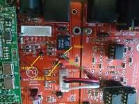
Hi Guanhao and Andrea ,- Do not not forget to cut the layer before placing the 0.1uF capacitor.
It might be interesting to have changes (cut , capacitor , .. and picture ) for AES input (Q18).
Br
Jacky
- Do not not forget to cut the layer before placing the 0.1uF capacitor.
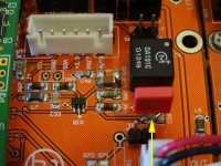
Yes, I did😀
Attachments
Last edited:
It might be interesting to have changes (cut , capacitor , .. and picture ) for AES input (Q18)
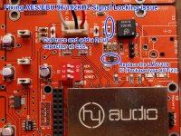
Based on misterwolf's findings, the solution for AES/EBU stated in this picture should work.
Attachments
Last edited:
please tel me the sound!
thank many many!
quanghao
I just elaborate what I know.
I do not have Toslink cable to test.
I have received today the DAC module and I have the same problem.
Lock only until 48KHz on COAX and AES/EBU input.
I have ordered a new pair of LMV7219 chips.
Lock only until 48KHz on COAX and AES/EBU input.
I have ordered a new pair of LMV7219 chips.
If you are using the DAC module without I/V jump you can follows my suggestion to eliminate one op-amp on the signal path- Do not not forget....
I have received today the DAC module and I have the same problem.
Lock only until 48KHz on COAX and AES/EBU input.
I have ordered a new pair of LMV7219 chips.
Hello Andrea ,
I ordered three new pairs of LMV7219 chips from Radiospare.
I tried to desoldering chips but it's not the right way to do it , one layer was also removed !
The best way is to cut chip with pliers, then desoldering the remaining.
If you have an other solution, please tell us.
Br
Jacky
Hello Andrea ,
I ordered three new pairs of LMV7219 chips from Radiospare.
I tried to desoldering chips but it's not the right way to do it , one layer was also removed !
The best way is to cut chip with pliers, then desoldering the remaining.
If you have an other solution, please tell us.
Br
Jacky
I think to use this method also if it is not easy cut this little pins
For desoldering always use solder wick. Makes it much easier.
I have used this method to solder but to desolder this is not easy
I have used this method to solder but to desolder this is not easy
Hi..
If there is to many pins on the chip for desolder, you could cut the pins one by one and then desolder the cutted pins from the solderpad.
After all pins has been desolderd, clean the solder pads for solder using solderwick.
Now the solder pad is ready for a new chip.
BTW: I'm lucky to have a Hot air solder/desolder system. This makes things a lot easier.
Hello Andrea ,
I tried to desoldering chips but it's not the right way to do it , one layer was also removed !
Some desoldering methods,
1) Drop in one big blob of solder onto the chip (covering all pins), then desolder it. Use soldering pump or wick to remove excess solder on PCB.
How to Remove SMD Resistors & Capacitors Using a Regular Soldering Iron - YouTube
OR
2) Cut all pins, remove chip, then desolder the pins
.
OR
2) Connect all pins on each side with solder, then use 2 soldering irons to desolder it.
OR
3) Use Chip Qick or Zephyrtronics LowMelt desolder wire.
SMD Removal using a Chip Quik kit - YouTube
Low Melt DeSolder Wire, Low-Temp SMD De-Soldering Removes Chip Quick & Easy
Last edited:
- Status
- Not open for further replies.
- Home
- More Vendors...
- Quanghao Audio Design
- DAC-END R (ES9018) full assembled board