Hi Mayday, The value you mentioned is pretty close and should work OK. The point of the resistor is to terminate the coaxial cable. That way the SPDIF signal won't be reflected back to the source. In an ideal world I would use whatever value matches your intended cable. I use a silver Teflon cable with 75 Ohm impedance. Matching it reduces jitter. Yes, the transformer could be jumpered. I ran mine that way for a while. I finally relented for galvanic isolation reasons to run it. I've heard no difference. I sourced my transformer from Digikey so I run a different equivalent part. Hope that helps...😀 Dave
I use 0,6mm silver wire with teflon tube for isolation as internal wiring in most builds(got a roll of 99,99% silver relatively cheap a few years ago). Never had the patience to make longer runs of it though. Thought I'd make a cheapish digital cable from a triaxial 75ohm(1m) cable. using 0,75m-1m and with rca connectors I should end up around 75R-78,6R.
I've ordered the DV709, so I'll use it. Galvanic reasons? Please explain.
/Jonas
Hi Mayday, Galvanic isolation just means that electrically the source and the DAC have isolation. That's what a transformer does. The grounds should also be seperated as this prevents ground loops. Make sure you use the insulator on the RCA jack to your chassis so that the ground remains isolated. I like the Neutric style connectors. If you can also use a star ground scheme in your DAC wiring. Dave 🙂
Hi Mayday, Galvanic isolation just means that electrically the source and the DAC have isolation. That's what a transformer does. The grounds should also be seperated as this prevents ground loops. Make sure you use the insulator on the RCA jack to your chassis so that the ground remains isolated. I like the Neutric style connectors. If you can also use a star ground scheme in your DAC wiring. Dave 🙂
Ok, thanks 🙂
Jonas Hi
Did you eventually load your TPR sufficiently and test the output voltage with an equivalent load of the 7220 ?
I'm going to have a go at building some myself but am concerned that it will only be useful for the RAM chip and 7310 looking again at the results posted.
What were your final feelings on this
Sorry it's from your other thread🙂
Jonas Hi
Did you eventually load your TPR sufficiently and test the output voltage with an equivalent load of the 7220 ?
I'm going to have a go at building some myself but am concerned that it will only be useful for the RAM chip and 7310 looking again at the results posted.
What were your final feelings on this
Sorry it's from your other thread🙂
Haven't gotten around to it since the CD-60 is waiting for caps.
Have tried ca 100mA with no issues though.
The TPR is supposed to be rather quiet, and simple enough to build.
It does need higher esr caps or resistors in series w caps w low esr.
Not really a drawback since those caps are the cheapest.
Don't remember the reason behind cap choise though.
The man from your other forum over there.....did he suggest it as being OK for 7220 ?
At 180 - 200 ma it'll just get bloody hot won't it ?
Bigger heatsinks then ?
These are 1.5 amp regulators - surely they'll be OK ?
I'm going to try it if I can find your BOM
At 180 - 200 ma it'll just get bloody hot won't it ?
Bigger heatsinks then ?
These are 1.5 amp regulators - surely they'll be OK ?
I'm going to try it if I can find your BOM
The man from your other forum over there.....did he suggest it as being OK for 7220 ?
At 180 - 200 ma it'll just get bloody hot won't it ?
Bigger heatsinks then ?
These are 1.5 amp regulators - surely they'll be OK ?
I'm going to try it if I can find your BOM
He said it would be fine, he has used similar but more complex designs for his own builds, don't remember what it was now, besides he did not want me to show it since it was all his design.
I'll see if I can find the bom, you can use a trimpot instead of the led's if you want.
C1 and C3 are cheapo elkos w high esr. NO connection between IC1 adj and in!!
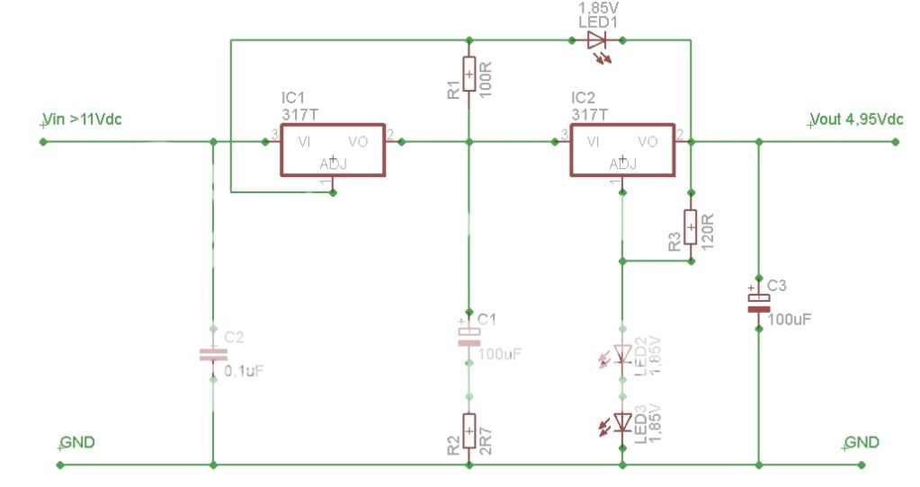
Led's are red, similar waveform to green.
Gave 4,73Vdc at 50mA and at 100mA so it should give that at 200mA too.
The reason for this is because I'm about three hours work away from attaching my external power supply.
In it is three 11.8 volt traff's. 3 bridges and three big smoothers.
DC at these caps is about 16.8 volts each.
I want to get this DC into the player via umbilical cable and then regulate the three supplies right on the chip with TPR's or something.
I've got some lovely P2P teddy regs I could use but dropping 16.8 down to 5v is unfair on the regs themselves.
It's not a healthy drop for them at all.
I could buy these cheapo LM317 based adjustable jobs from Hong Kong etc but then I have not built them myself and it's not DIY anymore.
Super regs at £ 40 each is the best way but I can't justify that to myself or the wife !! ( in that order !! )
Hoped someone might pop up with a super quiet home made thing with say 500ma ability that I could follow and understand !! ( and be very small )
Thanks - good BOM !!
I've got all that here except the led's - great.
Thanks a lot!
No problems mate 🙂
I'll order a 27R 3W resistor today, that will equal a 175mA load.
Need to get some stuff for the tube output anyways.
Need to get some stuff for the tube output anyways.
Thinking of getting a 6V/1,2A supply for the tube heater, that'll actually be cheaper than lowering the voltage with a power resistor.
Sometime next week I should have all I need to build the tube output, but I will listen to the DAC with opamps for a while before putting the tube output in. I feel it's important to have a basis for comparison.
Sometime next week I should have all I need to build the tube output, but I will listen to the DAC with opamps for a while before putting the tube output in. I feel it's important to have a basis for comparison.
Got the Rubycon ZA amongst other things today.
The small heatsinks are for opamp +-18V and should be enough.
Big is for SAA7220, still waiting for the rest of the heatsinks. Also fitted the Mundorf Mcap. Poor picture quality, will take better ones later.


The small heatsinks are for opamp +-18V and should be enough.
Big is for SAA7220, still waiting for the rest of the heatsinks. Also fitted the Mundorf Mcap. Poor picture quality, will take better ones later.


Not that much left to do now 🙂
Still a few parts to buy, but I can't afford that this month.

Btw, I was given an oscilloscope by the friend that gave me the B1(which is almost done now). It's rather old, but a proffesional piece of equipment that was used by an engineer at Ericsson(Now Sony Ericsson).
Still a few parts to buy, but I can't afford that this month.
Btw, I was given an oscilloscope by the friend that gave me the B1(which is almost done now). It's rather old, but a proffesional piece of equipment that was used by an engineer at Ericsson(Now Sony Ericsson).
A bit OT, but my sister found her ex's tube amp.
It malfunctioned, but I believe I can fix it with some help from friends.
I'll get it friday, anyone who knows what make and modell it is?

It malfunctioned, but I believe I can fix it with some help from friends.
I'll get it friday, anyone who knows what make and modell it is?
- Home
- Source & Line
- Digital Line Level
- DAC build TDA1541A/SAA7220P/B *will take som time*