I am more at home here.....😀
Walls padded enough for you? How do like your new jacket with eeextra long sleeves? 😉
I've been stuck here for months - it's a long sentence by the authorities.
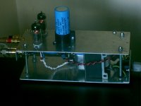
Did your new caps come for the CD60 - 7220 power ?
No, still waiting. But shipping times from HK/Taiwan etc seems to be a bit of a gamble.
The stuff ordered for the dac from the UK and germany arrived very fast. Waiting for more now...I believe, without having checked just now, that there's only transformers and opamps left to order.
Anyhow, I'm off to bed now...
Don't get as much sleep as I should, even w powerful painkillers my ankle is acting up and there's about a 2 month wait until I get to see a specialist.
Don't get as much sleep as I should, even w powerful painkillers my ankle is acting up and there's about a 2 month wait until I get to see a specialist.
Walls padded enough for you? How do like your new jacket with eeextra long sleeves? 😉
mmmm.....no
Short please !
My pay day is next Tuesday so I'm currently making lists too.
I love the build up to pay day !!
I hope I have something to post on the Arcam Alpha thread ( with pics ) very soon.
I'm nearly 8 weeks into it my new project and have another month to go I think.
I have been building an external ps, housed in another case which is the same case as my CD Player - so it's looks like it an Arcam PS
I've had to make a new facia panel to hide all the holes ( play, pause, stop, next etc )
It's looking good so far and when I connect it all up I'll have 6 transformers and 9 regulated power supplies in two boxes.
As you know well.. attention to detail costs a lot more than just DIY fun so it has taken longer than I wanted.
When I'm done I'll never touch the digital side of my system ever again - so much pain and expensive mistakes - mainly because of my lack of patience and knowledge.
This means if it is to be the last player I mod then I must maximise on every bit of it ( to my budget ) so I can bolt it down and forget it.
I don't want to be going back inside to bugger things up later on.
I've been experimenting with P2P ' teddy regs ' recently so I can fit them in tight spaces - they work great too.
I'll fire up some pics of those too very soon.
Andrew
Please do put up pics of your work!!
I'm thinking back and forth about building a valve outputstage using passiv I/V with a non-inductive 50R resistor/channel.
I've got a good schematic and just about all parts, but I don't understand tube-building-terminology...
Schematic is not made by me, but by another member on a Swedish forum. R12 will be 25W and screwed to the DAC-enclosure.

Which pin is for what for example.


I'm really keeping my fingers crossed some parts will come on Monday...getting bored.
Did a mock-up of how I'd fit the dual triode etc...


I'm thinking back and forth about building a valve outputstage using passiv I/V with a non-inductive 50R resistor/channel.
I've got a good schematic and just about all parts, but I don't understand tube-building-terminology...
Schematic is not made by me, but by another member on a Swedish forum. R12 will be 25W and screwed to the DAC-enclosure.
Which pin is for what for example.
I'm really keeping my fingers crossed some parts will come on Monday...getting bored.
Did a mock-up of how I'd fit the dual triode etc...
Last edited:
I'm actually starting to get a grip on how to hook up a tube according to the schematic above. 🙂
I'm interested in how this turns out Mayday as I've been looking into tubes myself. I built a Fetishizator (nine and simple) but I'm having balance issues with it so I've reverted back to op-amps for now. Would love to try tubes but like you I'm a little unsure about how it all hangs together! Keep us posted though - it's all looking good so far!
I'm interested in how this turns out Mayday as I've been looking into tubes myself. I built a Fetishizator (nine and simple) but I'm having balance issues with it so I've reverted back to op-amps for now. Would love to try tubes but like you I'm a little unsure about how it all hangs together! Keep us posted though - it's all looking good so far!
Tell me about it!
Even if I've been diy:ing for years, it's a bit like starting from scratch getting in to tubes...
I must have looked at the schematic, pics of pin config and lots more over and over for hours, but when you finally get it, it's not as "alien" as you thought.
Good thing w this circuit is that I only need to get a cheap 24V/1A wallwart to power it(high power resistor drops the voltage to 6V for the heaters). It needs no PCB, though I might do parts of it on veroboard instead of point to point since it is my first attemt.
I'll finish the DAC w opamps first, then put in the tubestage so I have something to compare to. I'll use AD797 for I/V and OPA134 for buffer/filter.
As buffer the AD797 is prone to oscillation unless you cut traces between pin2 and pin6 on the PCB and put a 100R resistor over the gap. So I've been told. This step is only for if you use AD797 and only for the second pair.
Looks like I'll complete the B1, but as a preamp and then sell it since I've been told by a few people it won't work in this design and I have already ordered the parts to complete it.
Schematic including the filter-part normally performed by the second pair of opamps.
Left is NOS, right is OS

Left is NOS, right is OS
The gate is the arrow, the upper line is the drain and the lower the source I think. Have a look here. It got me confused when I built my FET output stage as the pinout on the datasheet is from the underside if I remember correctly.
BTW - that engine is very cool! I remember reading about a guy building an exact working scale model of a Ferrari, that had a small v12 installed - this is it!
BTW - that engine is very cool! I remember reading about a guy building an exact working scale model of a Ferrari, that had a small v12 installed - this is it!
Last edited:
The gate is the arrow, the upper line is the drain and the lower the source I think. Have a look here. It got me confused when I built my FET output stage as the pinout on the datasheet is from the underside if I remember correctly.
BTW - that engine is very cool! I remember reading about a guy building an exact working scale model of a Ferrari, that had a small v12 installed - this is it!
Just figured it out using eagle a few minutes before I saw your post 🙂
Pinout is as seen from the underside of the fet?
Looking at the datasheet for 2SK170 it looks like pinout seen from the front(flat side) is: 1,2,3 or D,G,S.
I've seen the mini-ferrari video 🙂
- Home
- Source & Line
- Digital Line Level
- DAC build TDA1541A/SAA7220P/B *will take som time*