The 3300pF cap(C35) is marked omitted in my BOM, should I jumper or just leave holes as is?
Found ERO MKP's axial for the 2200pF and also found MKP's axial 2% for the 1000pF.
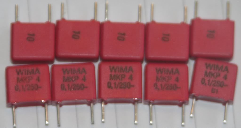
And last of the small ones, 10nF MKP axial
Found ERO MKP's axial for the 2200pF and also found MKP's axial 2% for the 1000pF.
And last of the small ones, 10nF MKP axial
Last edited:
The 3300pF cap(C35) is marked omitted in my BOM, should I jumper or just leave holes as is?
Found ERO MKP's axial for the 2200pF and also found MKP's axial 2% for the 1000pF.
And last of the small ones, 10nF MKP axial
Hmm, I actually have some nice russian mil.spec silver micas 1000pF.
Would these be even better?

Been looking around for parts.
Here's what I'm looking at atm...some choices seem obvious, others less so.
For the 10uf around the voltage regs:
Rubycon ZA 25V 22UF, Rubycon ZA 25V 10UF, Sanyo SEQP 20V 22UF(might be on the low side voltage? Don't know if unregulated voltage goes through them?) or Sanyo OS-CON SC 15uF 25VDC
For the 100uF around the voltage regs:
ELNA 25V 220UF RJF, Rubycon 270uF/35V ZLH, Rubycon 220uF/50V ZL
For 10uF around digital IC's:
Sanyo SC 16V 15UF
For 10uF around analog IC's:
Rubycon ZA 25V 10UF or Rubycon ZA 25V 22UF
Rectifier diodes:
BYV27-200
TCXO:
11.2896Mhz, 0,5ppm.
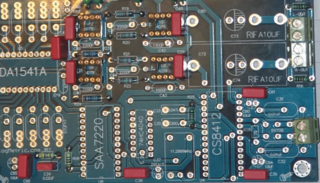
Hi Mayday - there is a resistor (R25) and a capacitor (C33) connecting pin 19 of the CS chip to ground, the missing cap C35 bypasses those so don't wire link it! It's probably optional, you could leave it out for now and then try it later.
It looks like that pin is the master clock output of the CS so, as you're reclocking, it's not required - those components ground it 'gracefully', I'm guessing the missing cap provides some additional filtering.
Careful though - I could be completely wrong! (I'm referring to the user guide posted earlier so confirm that we're talking about the same components!) Cheers.
Hi Mayday - there is a resistor (R25) and a capacitor (C33) connecting pin 19 of the CS chip to ground, the missing cap C35 bypasses those so don't wire link it! It's probably optional, you could leave it out for now and then try it later.
It looks like that pin is the master clock output of the CS so, as you're reclocking, it's not required - those components ground it 'gracefully', I'm guessing the missing cap provides some additional filtering.
Careful though - I could be completely wrong! (I'm referring to the user guide posted earlier so confirm that we're talking about the same components!) Cheers.
Thanks Josha.
Looked at a pic after that post and saw that they simply left it out.
Since I went with 1Kohm for R25, according to manual I'll need to go with CS8412 and 47nF for C33.
Found a nice MKP 47nF for C33 🙂
This will get pricy with the parts chosen so far, but I'll hopefully get the most out of the design.
This will get pricy with the parts chosen so far, but I'll hopefully get the most out of the design.
Planning a regulated PS for the SB Classic that will provide digital signal for this DAC.
So far I've decided to use a TPR but with LM350T instead of 317T(if possible).
6x2200uF before reg, BYV27-200 diodes.
1x6Vac(2,67A) transformer.
Is there such a thing as too much DIY? 😛
So far I've decided to use a TPR but with LM350T instead of 317T(if possible).
6x2200uF before reg, BYV27-200 diodes.
1x6Vac(2,67A) transformer.
Is there such a thing as too much DIY? 😛
NEVER 😀
I've been ' nearly finished ' for almost two years.
Just when I think I'm getting close someone here goes and posts something which makes me re think everything.
My amps and speakers have been finished for a year but this CD thing has really got a hold.
I'm in ' full rebuild ' mode on another better CD player and this MUST be my final one.
The stress is too much !!
Like you I'm trying to get the best bits I can afford....so it taking longer.
The good bit is it stops me from ' rushing in ' and ruining it as I've done before.
The cans I mentioned for screening the TCXO......I have 10 now.
Want one ?
Free... btw
NEVER 😀
I've been ' nearly finished ' for almost two years.
Just when I think I'm getting close someone here goes and posts something which makes me re think everything.
My amps and speakers have been finished for a year but this CD thing has really got a hold.
I'm in ' full rebuild ' mode on another better CD player and this MUST be my final one.
The stress is too much !!
Like you I'm trying to get the best bits I can afford....so it taking longer.
The good bit is it stops me from ' rushing in ' and ruining it as I've done before.
The cans I mentioned for screening the TCXO......I have 10 now.
Want one ?
Free... btw
Speakers I've really pleased w for a few years now.
The rest changes.
About best bits, I'd rather build this DAC once and do it right. It's ment to live in my system for a looong time hopefully.
Btw, you got a PM 🙂
CS8412/8414
Hi Mayday, On the input receiver chip use the values exactly as shown on the datasheet for the part your using. I didn't populate the capacitor you mentioned off pin 19. The resistor/capacitor value is a little critical and you don't need the extra cap shown in the Analogmetric build sheets. Just Google the CS8412 or CS8414 datasheet and use that value exactly. The CS8412 and CS8414 use different values. Hope that helps.... Dave😛
Hi Mayday, On the input receiver chip use the values exactly as shown on the datasheet for the part your using. I didn't populate the capacitor you mentioned off pin 19. The resistor/capacitor value is a little critical and you don't need the extra cap shown in the Analogmetric build sheets. Just Google the CS8412 or CS8414 datasheet and use that value exactly. The CS8412 and CS8414 use different values. Hope that helps.... Dave😛
Hi Mayday, On the input receiver chip use the values exactly as shown on the datasheet for the part your using. I didn't populate the capacitor you mentioned off pin 19. The resistor/capacitor value is a little critical and you don't need the extra cap shown in the Analogmetric build sheets. Just Google the CS8412 or CS8414 datasheet and use that value exactly. The CS8412 and CS8414 use different values. Hope that helps.... Dave😛
Since I used the 1Kohm resistor, I'll use 47nF for the capacitor and use CS8412.
I'll leave C35 unpopulated.
This also matches the datasheet for CS8412.
Thanks Dave.
My Wima 100nF/250V MKP4's (30pcs) are sitting at the post office now 🙂
I'll have to wait until tonight to collect them though.
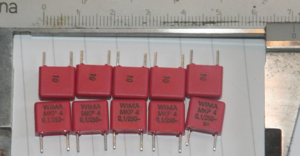
I think they are the best I can use that'll fit, although barely in some places...
Dimensions:
Width: 4,5mm
Hight: 9,5mm
Length: 10,3mm
RM/pitch: 7,5mm
I'll have to wait until tonight to collect them though.
I think they are the best I can use that'll fit, although barely in some places...
Dimensions:
Width: 4,5mm
Hight: 9,5mm
Length: 10,3mm
RM/pitch: 7,5mm
Nest step will be getting some more 100nF wima MKP(will be ordered Friday or Monday).
On Thursday I'll order:
1pc 76,8R
1pc 74HC4040N
MKP's 1uFx2, 220nFx2, 150nFx2, 33nFx6, 10nFx4, 47nFx1, 1nFx2.
DIP-16 and DIP-28 sockets.
On Thursday I'll order:
1pc 76,8R
1pc 74HC4040N
MKP's 1uFx2, 220nFx2, 150nFx2, 33nFx6, 10nFx4, 47nFx1, 1nFx2.
DIP-16 and DIP-28 sockets.
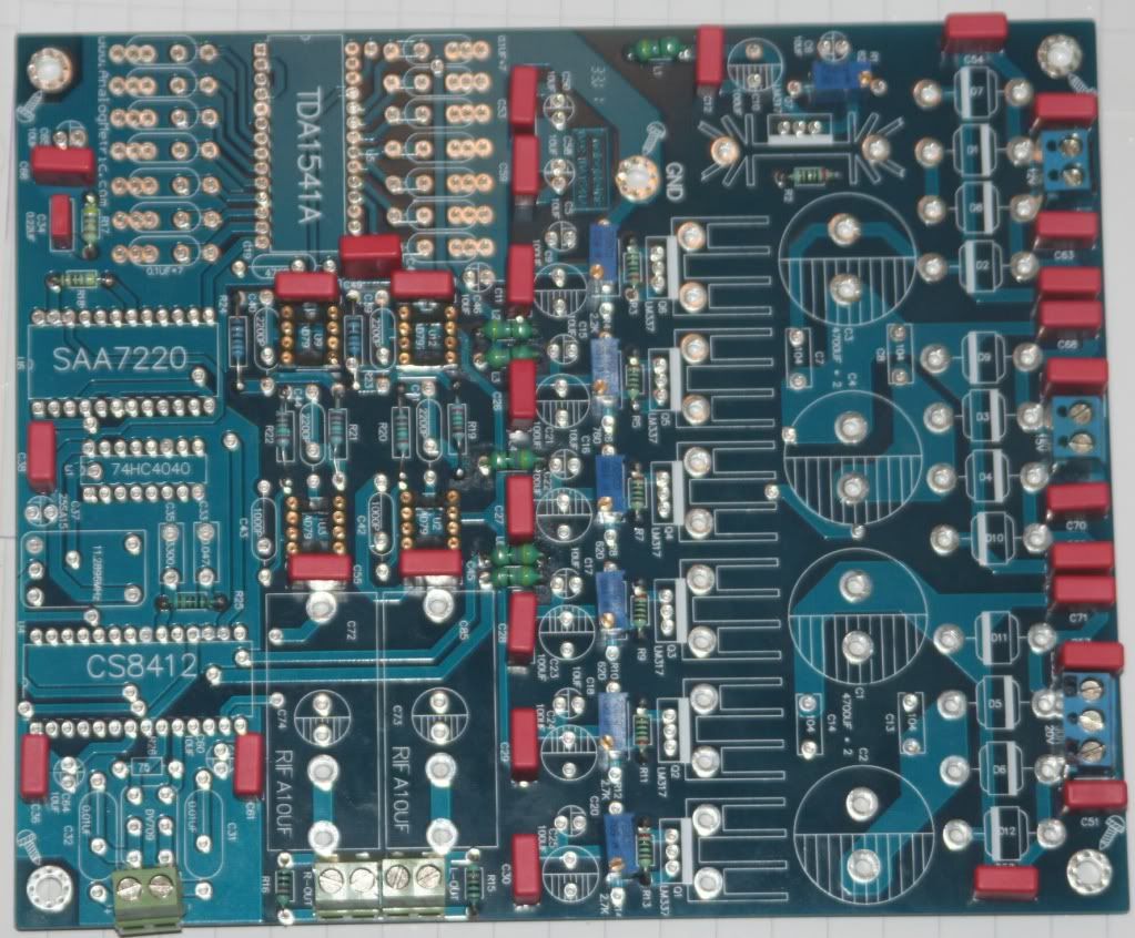
DAC
Hi Mayday, Looks like it is coming along very nice. Yesterday I modded my line stage (new Opamps). Today I installed the 120 pF capacitor at the DEM pins 16 and 17. Well... I must say this is not a subtle change. I used 120 pF 2% PPS SMT Panasonic. A complete change for the better. Thanks UV101 and Mayday. 😱
Hi Mayday, Looks like it is coming along very nice. Yesterday I modded my line stage (new Opamps). Today I installed the 120 pF capacitor at the DEM pins 16 and 17. Well... I must say this is not a subtle change. I used 120 pF 2% PPS SMT Panasonic. A complete change for the better. Thanks UV101 and Mayday. 😱
Hi Mayday, Looks like it is coming along very nice. Yesterday I modded my line stage (new Opamps). Today I installed the 120 pF capacitor at the DEM pins 16 and 17. Well... I must say this is not a subtle change. I used 120 pF 2% PPS SMT Panasonic. A complete change for the better. Thanks UV101 and Mayday. 😱
Thank you!
It's a rather big improvement, isn't it 🙂
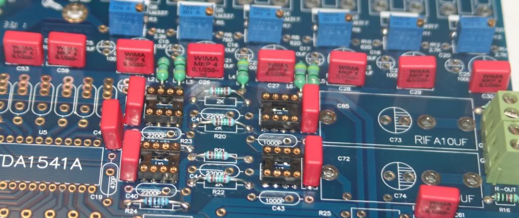
I've now found the exact values for TDA1541A decoupling caps.
pin 13,18, 2mA, fDEM /2, 1uF
pin 12,19, 1mA, fDEM, half current (13,18), twice the frequency of MSB, 250nF
pin 11,20, 0.5mA, fDEM / 2, half frequency, half current (12,19), 125nF
pin 10,21, 0.25mA, fDEM, half current double frequency (11,20), 31.25nF
pin 9,22, 0.125mA, fDEM / 2, half current, half frequency (10,21), 31.25nF
pin 8,23, 0.0625mA, fDEM, half current (9,22), 7,8nF
pin 7,24, 0.0625mA, fDEM, equal current (8,23), 7.8nF.
In practice, 1uF (MSB), 220nF, 120nF, 33nF, 33nF, 8.2nF, 8.2nF. This would give equal ripple currents
on all MSBs.
Will order these and some other items(more 100nF WIMA MKP's, DV709, the rest of the filmcaps and maybe some oscons, rubycon ZA and elna cerafine) tomorrow or on Thursday.
This build is getting much more expensive than the kit, but I believe I use much better components and I also believe this will show in the final result.


- Home
- Source & Line
- Digital Line Level
- DAC build TDA1541A/SAA7220P/B *will take som time*