Installed Vizual analyser a few days ago.
Today I got the "gadget" needed to connect between the probes and the soundcard. It connects to mic in.
Now all I need to do is learn how to use VA....
The box has diodes inside to protect the soundcard from voltage above 1,4V


Today I got the "gadget" needed to connect between the probes and the soundcard. It connects to mic in.
Now all I need to do is learn how to use VA....
The box has diodes inside to protect the soundcard from voltage above 1,4V
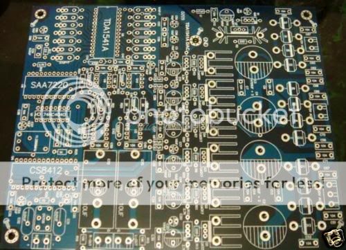
This how the PCB will be placed, all IC's as far away from the transformer as possible. 2 outputs for easy swapping between opamps and tube output. The cable is from an earlier project I planned for this enclosure, and will be re-done.
Got a nice green 220Vac LED that matches the retro look.
An externally hosted image should be here but it was not working when we last tested it.
Got a nice green 220Vac LED that matches the retro look.
An externally hosted image should be here but it was not working when we last tested it.
Hopefully I'll get the transformer and the TCXO this week, but that's if I'm lucky.
Sides and possibly front of the enclousure will be oak or similar, top will be black steel mesh(don't know if that's the word, steel plate with holes for ventilation).
Sides and possibly front of the enclousure will be oak or similar, top will be black steel mesh(don't know if that's the word, steel plate with holes for ventilation).
Hi
Another set of cans are their way this time with a typed address label
Fingers crossed this time
Another set of cans are their way this time with a typed address label
Fingers crossed this time
Hi
Another set of cans are their way this time with a typed address label
Fingers crossed this time
Thanks mate 🙂
Should get here soon then. I recieved a 2,5mm drillbit to drill holes for M3 tap.
Ordered it from the uk friday, got it today 🙂
Thats very fast 😕
Anyway, the cans are quite nice and fit exactly over the TCXO without touching other components or tracks. With some hot melt glue or epoxy resin they'll be perfect.
They even have a small removable lid.
I sent some spares this time so you can fit them in other machines too maybe.
Let me know when they arrive.
Thats very fast 😕
Anyway, the cans are quite nice and fit exactly over the TCXO without touching other components or tracks. With some hot melt glue or epoxy resin they'll be perfect.
They even have a small removable lid.
I sent some spares this time so you can fit them in other machines too maybe.
Let me know when they arrive.
Will do, and thanks again mate! 🙂
I've got shielded tubesockets and tubecaps as wel, so with a wall between the transformer and the rest...this should be a pretty well shielded dac 🙂
Sides temporarily screwed on, not pretty but it works for now...
An externally hosted image should be here but it was not working when we last tested it.
An externally hosted image should be here but it was not working when we last tested it.
Got a gift from the UK today, thanks Andrew!


I'll have to use my dremel and cut a small piece out to make it fit the PCB.
Thinking of using something as simple as bluetak to attach the can to the PCB.


I'll have to use my dremel and cut a small piece out to make it fit the PCB.
Thinking of using something as simple as bluetak to attach the can to the PCB.
Oh bugger ....I was thinking of the clock not the big dac - sorry !😱
It fits perfectly over the clock tcxo 🙂
Never thought of blutack - good idea
At least you got them this time - please about that and....they are not squashed....hahah
It fits perfectly over the clock tcxo 🙂
Never thought of blutack - good idea
At least you got them this time - please about that and....they are not squashed....hahah
There's chance of the can comming loose due to the blutack getting too hot?
Wouldn't want it to short anything out.
Wouldn't want it to short anything out.
TCXO has arrived today, very fast deliverys from vintage audio lab...I'm really impressed.
Just need to go to the postoffice to collect it.
Just need to go to the postoffice to collect it.


Made a socket for the TCXO.
Step 1
Step 2
In place but not soldered:
Step 1
An externally hosted image should be here but it was not working when we last tested it.
Step 2
An externally hosted image should be here but it was not working when we last tested it.
An externally hosted image should be here but it was not working when we last tested it.
In place but not soldered:
An externally hosted image should be here but it was not working when we last tested it.
Feels a bit nostalgic...I just did the last bit of soldering on the PCB.
TCXO socket now in place.
TCXO socket now in place.
An externally hosted image should be here but it was not working when we last tested it.
An externally hosted image should be here but it was not working when we last tested it.
An externally hosted image should be here but it was not working when we last tested it.
An externally hosted image should be here but it was not working when we last tested it.
An externally hosted image should be here but it was not working when we last tested it.
An externally hosted image should be here but it was not working when we last tested it.
This is where it started, feels a long time ago.
This is today:
The kit, with far inferior components than the ones I've chosen:
This is today:
An externally hosted image should be here but it was not working when we last tested it.
The kit, with far inferior components than the ones I've chosen:
An externally hosted image should be here but it was not working when we last tested it.
Started with the internal wiring.
Braided 0,6mm pure silver in PTFE tube. This is the internal digital wiring
This is close to how it will be when pcb is in place and the cable soldered in place.
Braided 0,6mm pure silver in PTFE tube. This is the internal digital wiring
An externally hosted image should be here but it was not working when we last tested it.
An externally hosted image should be here but it was not working when we last tested it.
This is close to how it will be when pcb is in place and the cable soldered in place.
An externally hosted image should be here but it was not working when we last tested it.
Hi Mayday, Your making good progress. Keep us posted. I have all the parts now for my second build minus the chassis or enclosure. I'm going to mount it on a bread board first and once I'm happy I will finish it off in a nice enclosure. 🙂 Dave BTW: I have been watching, just battled 2 different colds. Hope that's over now.....
- Home
- Source & Line
- Digital Line Level
- DAC build TDA1541A/SAA7220P/B *will take som time*