10 dB is about 3x, that's too little for what you want. For a line preamp, 10dB is quite OK, for a DAC it is not. 20db (10x) would pass for AD1865 and 300ohm I/V resistor.
That's where more stages of amplification go, or some tubes with higher amplification, ECC88, ECC81, ECC83, 6N2P and the like, there are a lot of them. There are also I/V options with a transformer that has amplification and then a tube gain stage.
I'm planning a PCM63 with 50ohm I/V and then a Mu Follower with 30x gain for 2.1VRMS. I can get that with the E88CC/6N1P-EV.
Last edited:
A few of us enthusiasts tried ad1865, ad1862 and pcm63 with tube output and they all sounded better than with any OPamp. Tubes: 6n6p, 6sn7, 7n7, c3g. We chose 6sn7 because it is more affordable than the better sounding c3g. We tried capacitors and transformers as output and of course the transformer sounds better.
50R is to much. Try different values.I'm planning a PCM63 with 50ohm I/V and then a Mu Follower with 30x gain for 2.1VRMS. I can get that with the E88CC/6N1P-EV.
“A few of us enthusiasts tried ad1865, ad1862 and pcm63 with tube output and they all sounded better than with any OPamp….”
You should add “in our system.”
It’s very subjective and all options should be open for exploration. Tube IV was very good for me but ultimately was not the “best” for my ears.
You should add “in our system.”
It’s very subjective and all options should be open for exploration. Tube IV was very good for me but ultimately was not the “best” for my ears.

My VHDL code is designed specially without the MCLK. For MCLD use you need new VHDL code. But explaining how to do it is out of the scope, because of how complicated it can be 🙂@miro1360
hello teacher
The TDA1541A code you provided
I want to modify it by OS version
We will use SAA7220P/B before CPLD.
Could you please tell me how?
Also, why isn't the CPLD's global clock a multiple of 44.1 and 48?
You need to grab and learn from existing things by testing:
https://forum.digikey.com/t/i2s-transceiver-vhdl/12845
https://github.com/dwjbosman/I2S_sender
In our systems and for us.“A few of us enthusiasts tried ad1865, ad1862 and pcm63 with tube output and they all sounded better than with any OPamp….”
You should add “in our system.”
It’s very subjective and all options should be open for exploration. Tube IV was very good for me but ultimately was not the “best” for my ears.
On the topic of grounding: I was always wondering where you are supposed to connect the ground from. I mean I connect PE to the chassis, that's clear.
But let's assume I've got an R-Core transformer, a PSU2 and the 1862 DAC, where on those boards are you supposed to grab the ground and connect it to the chassis?
My R-Core actually has got an N wire, so that's easy, but what about the PSU and the DAC board? Do I need to connect them to the chassis at all?
Right now there is no connection and everything's working. So what are the dangers or problems here?
(By the way: I noticed that with the Galaxy chassis from Modushop, there is no electrical connection between the separate parts due to painting and anodization and as such no connection from the parts on the front and back to the PE connection on the base plate. I'm in the process of creating some connections by filing off the paint, but I'm wondering, if that's really the solution.)
Have you tried any CFA op amps?A few of us enthusiasts tried ad1865, ad1862 and pcm63 with tube output and they all sounded better than with any OPamp. Tubes: 6n6p, 6sn7, 7n7, c3g. We chose 6sn7 because it is more affordable than the better sounding c3g. We tried capacitors and transformers as output and of course the transformer sounds better.
A tube with a passive I/V is nothing but a passive I/V with an additional amplifier, and the passive I/V determines the sound, not the amplifier (in this case the tubes). Changing the tubes in this case is equivalent to replacing the tubes in the preamp or amp. Everyone can like the other and that story has no end.
The only real solution for used tubes in the DAC is a grounded grid connection where the tubes really 'play' and the resistor in the cathode has such a small value that it no longer has any effect on the sound.
Thanks zoom777,
I guess I will have to purchase a unit or check out the website and see if it is available as a download.
For my knowledge, if I made a PS that had an output of 5V 800ma as a maximum, the JlSounds board would only draw what it needed, or does it not work that way ?
You posted at same time
I guess I will have to purchase a unit or check out the website and see if it is available as a download.
For my knowledge, if I made a PS that had an output of 5V 800ma as a maximum, the JlSounds board would only draw what it needed, or does it not work that way ?
You posted at same time
No, we haven't tried CFA op amp, any recommendations?Have you tried any CFA op amps?
I agree, but I personally like the sound of tube. Good passive I/V is good pasiv I/V. We tried a hand-wound non-inductive resistor and a transformer I/V. Like ANK kits.A tube with a passive I/V is nothing but a passive I/V with an additional amplifier, and the passive I/V determines the sound, not the amplifier (in this case the tubes). Changing the tubes in this case is equivalent to replacing the tubes in the preamp or amp.
We haven't tried this. Maybe someday. Honestly, we chose classic amplification because it avoids capacitors in the signal path. We also tried with a capacitor at the output, but then it colors the sound.The only real solution for used tubes in the DAC is a grounded grid connection where the tubes really 'play' and the resistor in the cathode has such a small value that it no longer has any effect on the sound.
@miro1360
you're right. Therefore, I would like to continue using this trigger type of code.
In any case, wouldn't it be advantageous to have a higher oscillator frequency as much as the CPLD specs allow?
How do I fix it with OS version?


I just want to do this...
It doesn't matter if it's not master clocking
you're right. Therefore, I would like to continue using this trigger type of code.
In any case, wouldn't it be advantageous to have a higher oscillator frequency as much as the CPLD specs allow?
How do I fix it with OS version?
I just want to do this...
It doesn't matter if it's not master clocking
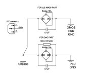
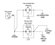
Ground the DAC to the box as I sketched. You have GND on PSU1/2, where the thick copper track is. The same is when you make a power supply for JLS. Ground the smaller 5V 100mA PSU together with PSU1/2 GND to the point where I wrote PSU GND, and the stronger 5V 400mA separately as in the sketch.On the topic of grounding: I was always wondering where you are supposed to connect the ground from. I mean I connect PE to the chassis, that's clear.
But let's assume I've got an R-Core transformer, a PSU2 and the 1862 DAC, where on those boards are you supposed to grab the ground and connect it to the chassis?
My R-Core actually has got an N wire, so that's easy, but what about the PSU and the DAC board? Do I need to connect them to the chassis at all?
Right now there is no connection and everything's working. So what are the dangers or problems here?
(By the way: I noticed that with the Galaxy chassis from Modushop, there is no electrical connection between the separate parts due to painting and anodization and as such no connection from the parts on the front and back to the PE connection on the base plate. I'm in the process of creating some connections by filing off the paint, but I'm wondering, if that's really the solution.)
The diode bridge (graetz bridge) serves to blow the fuse either in the DAC or on the distribution board in the event of a breakdown of the transformer's primary to secondary. It is a safety measure and should not be skipped. A 10A bridge blows a 16A fuse reliably. Diode bridge can be stronger than 10A.
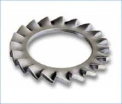
I had similar problems with the Modushop boxes and other boxes, some panels were not grounded due to plasticization or anodizing. The solution is simple, I put serrated elastic washers under few screws. The teeth dig into the metal and the GND connection is established.
For safety reasons, metal boxes must be completely and directly grounded to the safety GND of the power supply cable, i.e. the home safety grounding installation.
Attachments
Last edited:
I haven't tried anything yet. I'm waiting for others to try it and let me know what's good. 😉Have you tried any CFA op amps?
A tube with a passive I/V is nothing but a passive I/V with an additional amplifier, and the passive I/V determines the sound, not the amplifier (in this case the tubes). Changing the tubes in this case is equivalent to replacing the tubes in the preamp or amp. Everyone can like the other and that story has no end.
The only real solution for used tubes in the DAC is a grounded grid connection where the tubes really 'play' and the resistor in the cathode has such a small value that it no longer has any effect on the sound.
- Home
- Source & Line
- Digital Line Level
- DAC AD1862: Almost THT, I2S input, NOS, R-2R