Well, I tried my best to stay content with my current MiroDac setup and resist tweaking……
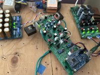
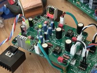
But, the recent chats about using the AD811 opamp as IV kept picking away at me. So, with lots of help from my friend for the pcb layout this IV board is ready for some listening. The circuit is inspired by Grunf’s adaptation of Walt Jung’s shunt regulator/AD811 IV work he shared here and on other threads. (Thank you Grunf!)
After some listened time and more tweaking I’ll share the gerbers via PM to those that are interested😉
Attachments

Thanks Vunce and Grunf.
I am in If really better than the 1656 or the 861 operational amplifiers.
As usual the power supply is one of the key.
I am in If really better than the 1656 or the 861 operational amplifiers.
As usual the power supply is one of the key.
Is there any version of Miro's board that allows using CF opamps, like the AD811?
And what about a version with TH shift registers?
And what about a version with TH shift registers?
On the topic of power supplies (@diyiggy), I built two Ubibs for Miro's AD1862 board - and the combo sounds fantastic. Now, looking at adding a FifoPiQ7 to the front end (no RPI), the question of power supply is coming up again, with batteries, super caps, super regs and shunts among the options. What do people on this thread use/prefer for 3.3v digital supply? Admittedly, I don't understand the technical/theoretical reasons for selecting one over the other.
Cheers -
Cheers -
i would stay away from battzeries and super caps because the mess and no real advantages at the end. would invest in a good r-core traffo and a proven reg design.
YMMV.
YMMV.
And you still don't believe that the AD811 is superior to other op amps as an I/V 😉Thanks Vunce and Grunf.
I am in If really better than the 1656 or the 861 operational amplifiers.
As usual the power supply is one of the key.
As far I have not compared it into my transparent system I can not say. All of those are also relative to the mix in the system...reg, passive parts. But I am open. If Vunce tells me the difference is not subtle then I try it as I am open.
Hi everyone .
is there a person who sell PCB boards?.
also populated with components already welded ?.
price ?
do you recommend a power supply (I only know superreg : https://diyaudiostore.com/products/super-regulator?_pos=1&_sid=c70b52e36&_ss=r) and an I/V output stage ?
Hello and thanks
is there a person who sell PCB boards?.
also populated with components already welded ?.
price ?
do you recommend a power supply (I only know superreg : https://diyaudiostore.com/products/super-regulator?_pos=1&_sid=c70b52e36&_ss=r) and an I/V output stage ?
Hello and thanks
@arivel the Gerber files are available for you to order your own boards .The output stage (IV) is already on the board. And of course you can use an external IV stage. Refer to post #1. All the DAC and PSU information are there for you to make your own boards.
Exactly .
post n 1 is updated on any , and I stress EVENTUAL , problems , errors or on the contrary improvements that have emerged in all these pages and interventions by myriads of people ?.
post n 1 is updated on any , and I stress EVENTUAL , problems , errors or on the contrary improvements that have emerged in all these pages and interventions by myriads of people ?.
That would be for PCM58, and it has been fixed. Like what Brijac said, the information posted in post #1 is conscientiously updated by Miro.I read somewhere in this thread that a problem existed with a capacitor having reversed polarity. Can you confirm that this issue was later solved in post #1?
Which software tool(s) was/were used to produce the Gerber Files? Do you have a schematic file for back annotation?
for those wishing to use AES3 instead of SPDIF for the digital to I2s converter, it is possible to use INA165x combined with one of the many DIR9001 boards on sale that have SPIDF input?. perhaps it would be enough to remove the coaxial connector and solder the INA165x outputs directly on the board by sharing ground.
https://www.ti.com/lit/ds/symlink/i...2Famplifiers%2Fline-receivers%2Fproducts.html
https://www.ti.com/lit/ds/symlink/i...2Famplifiers%2Fline-receivers%2Fproducts.html
I did not quite understand, could you please send a schematic or block diagram?for those wishing to use AES3 instead of SPDIF for the digital to I2s converter, it is possible to use INA165x combined with one of the many DIR9001 boards on sale that have SPIDF input?. perhaps it would be enough to remove the coaxial connector and solder the INA165x outputs directly on the board by sharing ground.
https://www.ti.com/lit/ds/symlink/i...2Famplifiers%2Fline-receivers%2Fproducts.html
look at figure 51 and figure 58 of the datasheetI did not quite understand, could you please send a schematic or block diagram?
Ok, but if I understood correctly, that circuit, based on the INA165x, is designed for balanced audio analog signals, not for the digital AES3 protocol, but maybe I'm wrong.
The 3 pin XLR connector can be used both for analog or digital audio interfaces.
https://en.wikipedia.org/wiki/XLR_connector
The 3 pin XLR connector can be used both for analog or digital audio interfaces.
https://en.wikipedia.org/wiki/XLR_connector
- Home
- Source & Line
- Digital Line Level
- DAC AD1862: Almost THT, I2S input, NOS, R-2R