The markings on this chip looks different from those supplied by Rochester. Dubious? Or simply different period made?

i do have a pair from group buy here. But casually hunting for perhaps some spares and chanced upon the Chinese source. I am just wondering if the markings is of correct standard (yes, i know that does not guarantee it is a real AD1862). Will try out if at least the physical attributes are correct for a start. If AD does not have such markings in the first place, then it is not worth a gamble at all.@zoom777 Today prices for AD1862 from china are crazy. It is better if you buy it from a group buy and you can get 100% new chip.
Buy AD1862 from china only if you get a good offer (like under 12€ per piece) ... I did not found this price anywhere today 🤣
and yes, they are around 12 euro or so. from the pins on the pic , they do not look new. Great for testing new build if they are genuine at least.i do have a pair from group buy here. But casually hunting for perhaps some spares and chanced upon the Chinese source. I am just wondering if the markings is of correct standard (yes, i know that does not guarantee it is a real AD1862). Will try out if at least the physical attributes are correct for a start. If AD does not have such markings in the first place, then it is not worth a gamble at all.
Last edited:
It seems to me that each serie had different print style, so this one can be genuine (not new, but can be working) 😉

Last Night a DJ Saved My Life
Song by Indeep, maybe the best disco song of all times.
🤣
Song by Indeep, maybe the best disco song of all times.
🤣
yep that was that one, that was my young days, however I was more a teenager that was listening 70s' to 80's british music, world and jazz...few classic as well since ! ahaha I had time to play with turntables, cd players and DACS since !
Certainly in the 5 top disco five with Staying Alive (yet a story of life safe!) , Dancing Queen and at least one of CHIC ! (limit funk here though)
PaddyGarcia member was very nice to help by several dac chips group buy 🙂
Certainly in the 5 top disco five with Staying Alive (yet a story of life safe!) , Dancing Queen and at least one of CHIC ! (limit funk here though)
PaddyGarcia member was very nice to help by several dac chips group buy 🙂
Last edited:
Damn, I realise in a sorta of awarness for that floppy middle of the week than the Disco mvt had a problem with "life" concept, following the idea of the best tittles already talked above: once more for illustration : Diana Ross "I will survive" !
Could it be than Disco has blues legacy in fact in spite of the late 70's funny new-yorkers dancing mvt it was ??? Certainly a conversation that deserves a Lounge question... not wanting an ABBA troller more than that ! (It should be borring in Russia though, lol, all that westerners that prefers peace are degenrated ! At the end when you drive a tank, weeds or Vodka once must choose... ok sligthy off topic because my galle drug, that is wine... roman fault I am innocent !)
Could it be than Disco has blues legacy in fact in spite of the late 70's funny new-yorkers dancing mvt it was ??? Certainly a conversation that deserves a Lounge question... not wanting an ABBA troller more than that ! (It should be borring in Russia though, lol, all that westerners that prefers peace are degenrated ! At the end when you drive a tank, weeds or Vodka once must choose... ok sligthy off topic because my galle drug, that is wine... roman fault I am innocent !)
Last edited:
shame on me... it was Gloria Taylor !
hope you will forgive me, and to help just a disco more :
Pffff, all what I have to do here in between Miro drops here his TDA1541A....
NOS...that's the way , ah ah, I like it, aha aha...

hope you will forgive me, and to help just a disco more :
Pffff, all what I have to do here in between Miro drops here his TDA1541A....
NOS...that's the way , ah ah, I like it, aha aha...
Does the TDA1541 have offset output current ? Or similar to AD or PCM ?
If yes to offset current, is it stable over tm ?
How do you compensate for it ?
Patrick
If yes to offset current, is it stable over tm ?
How do you compensate for it ?
Patrick
Last edited:
Bravo Miro, that is not easy to make a TDA1541A project... this chip is a little diva able of the best as the worst according the layout and surrounding !
Just a tip though, if the big caps are the ones for the DEM, the sounding quality will profit of a very less inductance, i.e. reduced length between cap legs...
Also the Taiwann 97 you have is on the clear and has more ligth in the sound (not being brigth tough) than the current younger model most of people own... voicing with parts is different. Yours should mix fine with the little velvett sound of the opa627 but maybe too ligth with your usual LM reference ! Be aware, the rythmic section of this particular Taiwann since done well in the power supply is addictive... it digged them all I heard, discrete R2R were old donkeys there in front of that wilde horse 🙂 !
Last edited:
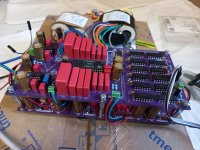
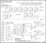
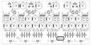
DAC TDA1541A by miro1360 😎
The long-promised DAC. I will put it in this thread because it follows the same topology as my other DACs, so you can objectively compare the sound.
The space around I/V opAmp should has enough space for sparkos and similiar opAmps.
Use only high quality components from trusted sources (especially logic ICs (and use only 74HCTxx family), capacitors and opAmps) ... TDA1541A from a CD player or eBay (this was my source).
CF1, CF2 is PP capacitor which should serve as an output filter (I didn't use it).
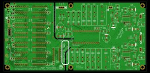
Build hints:
Power supply is shared in the next post and PCB has the same dimension (can be stacked).
After many tests, I decided to do it first with 78/79xx regulators from onsemi (I think these have an excellent sound, but you need try).
Of course any other regulator can be used here, but I highly recommend separating not only power supplies, but also their grounds (+5VD/GND1, +5VA/GND2/-5VA, -15VA/GND3, +12VA/GND4/-12VA .... GND1,2,3,4 are not connected together on the power supply, because they are connected on the DAC PCB). Therefore in the best case scenario, each power supply should have its own transformer winding.
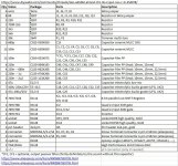
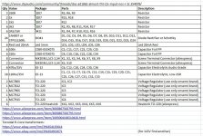
BOM example:
https://www.mouser.com/ProjectManager/ProjectDetail.aspx?AccessID=6c165f3903
https://www.aliexpress.com/item/4000867583795.html (2-Pin)
https://www.aliexpress.com/item/4000867583795.html (3-Pin)
Enjoy the sound fellas
- NOS, without digital filter
- simultaneous mode (input logic converts data from I2S)
The long-promised DAC. I will put it in this thread because it follows the same topology as my other DACs, so you can objectively compare the sound.
The space around I/V opAmp should has enough space for sparkos and similiar opAmps.
Use only high quality components from trusted sources (especially logic ICs (and use only 74HCTxx family), capacitors and opAmps) ... TDA1541A from a CD player or eBay (this was my source).
CF1, CF2 is PP capacitor which should serve as an output filter (I didn't use it).
Build hints:
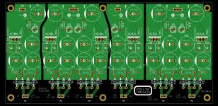
- start with wire jumpers (let paper thin space between wire jumper and PCB)
- install all resistors, digital chips, C1-C15 capacitors, sockets, connectors, trimmers, film capacitors and big electrolytes
- carefully with digital chips, don't mix them up
- triple check electrolytes for the correct polarity (otherwise they explode)
- triple check everything (especially solder joints (cold joints, bridges), logic ICs positions)
- put on safety glasses, connect power supplies and measure supply voltages on the pins in the sockets (IC14: pins 15, 26, 28 ... OP1 and OP2: pins 4, 7)
- if everything is fine, disconnect power supplies and discharge all capacitors (insert 330R resistor between each power supply pin and GND directly on each power connector)
- only after that install TDA1541A and opAmps into sockets
- connect your I2S device (mine works with PCM2706, but you can use any)
- put on safety glasses, connect power supplies and wait ... now carefully wait for possible problems (smoke, buzzing, explosions)
- if nothing happens, touch all the electrolytic capacitors with your finger, they should be cold
- measure DC voltage on the output connectors (L-OUT, R-OUT) and set it with trimmers to 0V (set as much as you can, if it doesn't go to zero, it doesn't matter yet)
- turn it off
- insert 100R resistors (or similiar) into output connectors
- turn it on, play some music into resistors 🤣 and let it warm up for at least 20 minutes
- stop the music, disconnect 100R resistors and again measure DC voltage on the output connectors and trim it
- turn it off and wait for about 10 seconds
- turn it on and again measure DC voltage on the output and trim it again as best as you can (now it should be at null ... if the null is out of reach (lets say <1V) then it could be achieved by modifying R20/R21 values)
- try the music on your speakers or headphones
- when you turn it on next day, measure DC voltage on the output again (after warm up) ... a few mV fluctuation is normal ... it highly depends on the power supply stability (if the voltage moves after warm up, so does this DC offset ... a more precise DC offset solution can be installed instead of resistors on the appropriate pins - but be careful because the sound is affected by this)
Power supply is shared in the next post and PCB has the same dimension (can be stacked).
After many tests, I decided to do it first with 78/79xx regulators from onsemi (I think these have an excellent sound, but you need try).
Of course any other regulator can be used here, but I highly recommend separating not only power supplies, but also their grounds (+5VD/GND1, +5VA/GND2/-5VA, -15VA/GND3, +12VA/GND4/-12VA .... GND1,2,3,4 are not connected together on the power supply, because they are connected on the DAC PCB). Therefore in the best case scenario, each power supply should have its own transformer winding.
BOM example:
https://www.mouser.com/ProjectManager/ProjectDetail.aspx?AccessID=6c165f3903
https://www.aliexpress.com/item/4000867583795.html (2-Pin)
https://www.aliexpress.com/item/4000867583795.html (3-Pin)
Enjoy the sound fellas
Attachments
Finally! Thank you !DAC TDA1541A by miro1360 😎
- NOS, without digital filter
- simultaneous mode (input logic converts data from I2S)
The long-promised DAC. I will put it in this thread because it follows the same topology as my other DACs, so you can objectively compare the sound.
The space around I/V opAmp should has enough space for sparkos and similiar opAmps.
Use only high quality components from trusted sources (especially logic ICs (and use only 74HCTxx family), capacitors and opAmps) ... TDA1541A from a CD player or eBay (this was my source).
CF1, CF2 is PP capacitor which should serve as an output filter (I didn't use it).
Build hints:
...
- start with wire jumpers (let paper thin space between wire jumper and PCB)
- install all resistors, digital chips, C1-C15 capacitors, sockets, connectors, trimmers, film capacitors and big electrolytes
- carefully with digital chips, don't mix them up
- triple check electrolytes for the correct polarity (otherwise they explode)
- triple check everything (especially solder joints (cold joints, bridges), logic ICs positions)
- put on safety glasses, connect power supplies and measure supply voltages on the pins in the sockets (IC14: pins 15, 26, 28 ... OP1 and OP2: pins 4, 7)
- if everything is fine, disconnect power supplies and discharge all capacitors (insert 330R resistor between each power supply pin and GND directly on each power connector)
- only after that install TDA1541A and opAmps into sockets
- connect your I2S device (mine works with PCM2706, but you can use any)
- put on safety glasses, connect power supplies and wait ... now carefully wait for possible problems (smoke, buzzing, explosions)
- if nothing happens, touch all the electrolytic capacitors with your finger, they should be cold
- measure DC voltage on the output connectors (L-OUT, R-OUT) and set it with trimmers to 0V (set as much as you can, if it doesn't go to zero, it doesn't matter yet)
- turn it off
- insert 100R resistors (or similiar) into output connectors
- turn it on, play some music into resistors 🤣 and let it warm up for at least 20 minutes
- stop the music, disconnect 100R resistors and again measure DC voltage on the output connectors and trim it
- turn it off and wait for about 10 seconds
- turn it on and again measure DC voltage on the output and trim it again as best as you can (now it should be at null ... if the null is out of reach (lets say <1V) then it could be achieved by modifying R20/R21 values)
- try the music on your speakers or headphones
- when you turn it on next day, measure DC voltage on the output again (after warm up) ... a few mV fluctuation is normal ... it highly depends on the power supply stability (if the voltage moves after warm up, so does this DC offset ... a more precise DC offset solution can be installed instead of resistors on the appropriate pins - but be careful because the sound is affected by this)
Power supply is shared in the next post and PCB has the same dimension (can be stacked).
After many tests, I decided to do it first with 78/79xx regulators from onsemi (I think these have an excellent sound, but you need try).
Of course any other regulator can be used here, but I highly recommend separating not only power supplies, but also their grounds (+5VD/GND1, +5VA/GND2/-5VA, -15VA/GND3, +12VA/GND4/-12VA .... GND1,2,3,4 are not connected together on the power supply, because they are connected on the DAC PCB). Therefore in the best case scenario, each power supply should have its own transformer winding.
BOM example:
https://www.mouser.com/ProjectManager/ProjectDetail.aspx?AccessID=6c165f3903
https://www.aliexpress.com/item/4000867583795.html (2-Pin)
https://www.aliexpress.com/item/4000867583795.html (3-Pin)
Enjoy the sound fellas
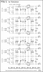
PSU 1 for DAC TDA1541A by miro1360
Use only high quality components (low ESR and Audio capacitors).
78/79xx regulators from onsemi (MC78xx/MC79xx, be sure you get these).
You are working with mains voltage, so very careful because it can be deadly and no one is here responsible for your life and health
Build hints:
BOM example:
https://www.mouser.com/ProjectManager/ProjectDetail.aspx?AccessID=2e5d5e6ab6
https://www.aliexpress.com/item/4000867583795.html (2-Pin)
https://www.aliexpress.com/item/4000867583795.html (3-Pin)
https://www.aliexpress.com/item/1005004106510428.html (15x10x20mm)
https://www.ebay.com/itm/391654135614
https://www.ebay.com/itm/391654923671 (for 115V find another)
https://www.aliexpress.com/item/1005004127890102.html (35mm M3 screw spacer)
https://www.aliexpress.com/item/1005003411992910.html (M3 screws)
maybe a few M3 gaskets ...
...
- PCB has the same dimensions as DAC, so it can be stacked
- Grounds are already separated for best results (connected in DAC PCB)
Use only high quality components (low ESR and Audio capacitors).
78/79xx regulators from onsemi (MC78xx/MC79xx, be sure you get these).
You are working with mains voltage, so very careful because it can be deadly and no one is here responsible for your life and health
Build hints:
- start with diodes, resistors, connectors, LEDs, foil capacitors, big electrolytes
- install heatsinks on regulators and put them into PCB (let a small space between heatsink and PCB)
- triple check electrolytic capacitors polarity
- install AC wires from transformers (you can first try them and measure AC voltages)
- triple check everything (especially solder joints (cold joints, bridges), regulator ICs positions)
- put on safety glasses, turn it on and hide for a while (watch for smoke or explosions LOOL 🤣)
- if nothing bad happens, touch electrolytic capacitors if they are cold (touch also heatsink - it should be cold or light warm because there is small current consumption yet)
- now measure DC output voltages (and also AC input voltages)
- turn it on and off a few times, everything should work without further settings
BOM example:
https://www.mouser.com/ProjectManager/ProjectDetail.aspx?AccessID=2e5d5e6ab6
https://www.aliexpress.com/item/4000867583795.html (2-Pin)
https://www.aliexpress.com/item/4000867583795.html (3-Pin)
https://www.aliexpress.com/item/1005004106510428.html (15x10x20mm)
https://www.ebay.com/itm/391654135614
https://www.ebay.com/itm/391654923671 (for 115V find another)
https://www.aliexpress.com/item/1005004127890102.html (35mm M3 screw spacer)
https://www.aliexpress.com/item/1005003411992910.html (M3 screws)
maybe a few M3 gaskets ...
...
Attachments
I tried a few ... simple resistor split with smoothing capacitor (the best sound), jfet+resistor (it softened the music a bit, not good), CCS transistor with LED diode (good sound but sometimes problems with DC stability), 2 transistors ccs cage (problems with DC stability) ... so a simple resistor with stable power supply did the job 🤓Does the TDA1541 have offset output current ? Or similar to AD or PCM ?
If yes to offset current, is it stable over tm ?
How do you compensate for it ?
Patrick
There is enough space for another experiments 🙂 So far it is stable (+-2mA after warm-up, a few days testing) ... A DC servo would be nice but this affects the sound as it constantly does something ...
When you use resistor bias, how much DC drift do you see at the IV output ?
With 1.5k Riv, 1µA DC change is 1.5mV.
Or you have to wait for the TDA to warm up first ?
I mean even if your bias current is absolutely stable, how stable is the offset current of the TDA ?
Patrick
With 1.5k Riv, 1µA DC change is 1.5mV.
Or you have to wait for the TDA to warm up first ?
I mean even if your bias current is absolutely stable, how stable is the offset current of the TDA ?
Patrick
- Home
- Source & Line
- Digital Line Level
- DAC AD1862: Almost THT, I2S input, NOS, R-2R