Hi,
What type of resisfor did you choose as I/V ? What caps on board ? Maybe a picture?
These time I am testing the opa1611 , the sound is keeping this softness but results differ with resistor at iso caps decoupling conf. No surprise, but maybe the not said good wirewound at i/V task sounds a little clearer, more natural than plain normal metal films, though I have several yet to test...the Allen Bradeley has a good tonal but I can hear them distorss with the brass instruments (sort of fqtiguing harshness with trumpets for instance but which perhams is conform with reality ?!)

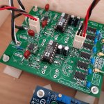
Interesting board you have ;-) For some it might look, that you still have to solder a lot of parts before finishing it ;-D
Nah it is all at the bottom...
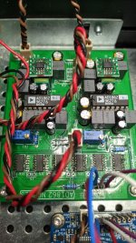
Lytics are under the 0,1 uF areas.
47 uF filter cap is a 27 uF Fc with a pitch leads of 1 mm, less than the gap of the two ic adaptator on which it is soldered with 2 mm leads length in order to minimize stray inductance. Pin1 cap filter has the same pitch betwen the two legs and are Vishay SAL orange thinghy cause I had some but hqs to be changed with something more adapted.
The only part really missing in the photograph is the i/v resistor as it is my testing board and also the pots matching circuitry.
Edit: the small one are CDE FCA 0,15 uF/16V, minimal inductance, there is a copper wire betwen the pad qnd the gnd vias..soldering flux is my friend and magnyfing glass... FC caps 3mm pitch just at the bottom...small ground loop, enhanced inductance maybe...
I consider it not optimal...work in progress with passive parts, tube to come for it or for the aya with the help of gaszto member from this thread...
Ok, thanks, yet I would like to have one supporting the boards footprint!! Any chance?
Almost impossible 🙁 There are many receivers and each has another shape.
Perhaps if you find GP1FAV30RK0F somewhere, I did not find it to buy.
Ernest I have the GP1FAV50RK0F here (UK) if you want one sending. Maybe it will work on 3v3 or maybe cut a trace and feed separate 5v.
Or....absolute max on the WM8804 is 5v and the 5v receiver will work at a lower voltage. Maybe use 4v for the 3v3 IC2 rail?
But please don't pop your 8804!, I am just summising after looking at the data sheets
Or....absolute max on the WM8804 is 5v and the 5v receiver will work at a lower voltage. Maybe use 4v for the 3v3 IC2 rail?
But please don't pop your 8804!, I am just summising after looking at the data sheets
Last edited:
Hi Jim, thanks a lot for the offer, I appreciate this. And, I have one as well and have started thinking, how I could implement it. Trying 3.3V was on my plan and also feeding it with separate 5V. I am misdi g a few parts, the usual non availability... So I have time.
Again, thanks for your offer! Cheers
Again, thanks for your offer! Cheers
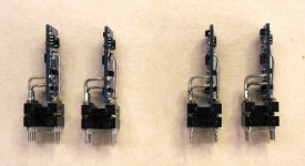
The new JFET-based FC CEN IV that was posted here was sent out for audition :
https://www.diyaudio.com/community/...st-tht-i2s-input-nos-r-2r.354078/post-6989903
After many enjoyable hours of critical listening, so I was told, both IVs were killed by a fancy power supply it was not designed to take.
Complete burn-out of the input stage, including those unobtanium JFET-pairs.
So they came back and now have been fully repaired, and also modified to make them more robust against any future abuse.
Also built another pair for 12V rails for direct plug in.
But Riv and Civ still need to be removed.
Not 100% plug & play.
(The lower DIP IC socket is only there to protect the gold-plated pins of the DIP header.)
Cheers,
Patrick
.
Attachments
What PSU Patrick?
Is this a moot project if unobtainiums on the BOM or will there be alternatives?
Thanks
Is this a moot project if unobtainiums on the BOM or will there be alternatives?
Thanks
"Is this a moot project if unobtainiums on the BOM"
I beg your pardon.
Did I ever say it would become a public project ?
Am I not allowed to build whatever I want ?
Are AD1862, AD1865, PCM56, PCM1704, ..... not all obsolete ?
Cheers,
Patrick
I beg your pardon.
Did I ever say it would become a public project ?
Am I not allowed to build whatever I want ?
Are AD1862, AD1865, PCM56, PCM1704, ..... not all obsolete ?
Cheers,
Patrick
Nice analogue electronic devices are disappearing day by day.
In a few months time, there will be even less devices left.
Unless one is happy with what IC manufacturers can offer, unobtaniums will be unavoidable.
We are lucky that people like Nelson is keeping DIY alive by letting the forum to offer part of his reserves.
You can of course just use opamp and be happy with.
Not that you don't get decent sound with little expense.
Patrick
- Home
- Source & Line
- Digital Line Level
- DAC AD1862: Almost THT, I2S input, NOS, R-2R