Decek, it's a very clean casing, kuddos 🙂 . Well done for the R-Core traffo.
Just a little detail perhaps: however a thing could be improved : if you flip the dac board 180° you can make very short link between the usb board and the dac board which can give subtle but hearable effects often (I2S and jitter live better when it's short) and it doesn' matter if the wires for the RCAs output are longers to acheive that.
@ Miro : could it be fun to link for the newbies some link towards several R-Core traffos ?
Thanks for the hint, I will implement that soon. Cheers.
Here I created the stop-clock for standard I2S (BCK 64fs)
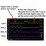
Great! Please see also the stopped clock logic shown here!
For your reference, I found this graph that I believe was originally posted by diyinhk on some audio forum a few years ago:
View attachment 999633
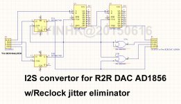
@Hidy, how the stop-clock can be the only way to eliminate the noise, when the clock is not stopped for one channel? 😀 When you see the "Reclock jitter eliminator" schematic, CLKR is active all the time 😕
The schematic shows, it is not reclock, but more like a try for resynchronizer (if the MCLK will not be too fast to resynchronize). The jitter in BCK or LRCK is not eliminated by this circuit 🙁
Hi miro,
With the stop clock mechanism, the clock should be stopped on both channels. I saw a graph posted by diyinhk a few years ago to demonstrate this. I could see that the signals on both channels were ruler flat once stopped. However, I couldn't find that post anymore. Maybe someone else would be able to find it.
The graph I posted today was actually from somewhere else, that resembled diyinhk's original graph, but like you said that clocks were not stopped at all on either channel there.
This is the right graph from diyinhk ad that shows clock for both channels are stopped.

I found this graph from here: DIYINHK AD1865 I-out vraagje - Pagina 5 - forum.zelfbouwaudio.nl

I found this graph from here: DIYINHK AD1865 I-out vraagje - Pagina 5 - forum.zelfbouwaudio.nl
@ Miro : could it be fun to link for the newbies some link towards several R-Core traffos ?
I linked the 30W one from eBay 😀
You can see here, the purple clock is not stopped 🙂 (original diyinhk post)
I also wondered about that, but maybe purple is DIN and blue is DOUT...
He added this description in his next post:
Yellow: LATCH for left and right DAC
Cyan: DATA for left and right DAC
Purple: Right clock
Blue: Left clock
Yellow: LATCH for left and right DAC
Cyan: DATA for left and right DAC
Purple: Right clock
Blue: Left clock
Hi miro and all,
Help needed!
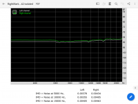
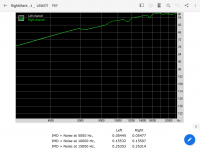
Today I did some measurements with my two ad1862 dacs and found that my diyinhk dac measures slightly better. However, there is a huge difference in the last test. It is the IMD (Swept Tone) test. My diyinhk dac got an Excellent. But my miro's dac only got a miserable Average.
I repeated the test many times and the results were consistent.
Here are some of my test files.
Diyinhk ad1862
View attachment RightMark Audio Analyzer test _ [DirectSound] diyinhk ad1862 isolated.pdf
My miro's ad1862 with LM6171
View attachment RightMark Audio Analyzer test _ LM6171.pdf
IMD Swept Tone with diyinhk dac

IMD Swept Tone with my miro's dac

I wonder what's causing my miro's dac to perform so poorly in the IMD test? Can someone measure your dac and let me know how your dac perform in the IMD test?
Also, any advice / suggestions on improving on the IMD performance?
Thank you.
Help needed!
Today I did some measurements with my two ad1862 dacs and found that my diyinhk dac measures slightly better. However, there is a huge difference in the last test. It is the IMD (Swept Tone) test. My diyinhk dac got an Excellent. But my miro's dac only got a miserable Average.
I repeated the test many times and the results were consistent.
Here are some of my test files.
Diyinhk ad1862
View attachment RightMark Audio Analyzer test _ [DirectSound] diyinhk ad1862 isolated.pdf
My miro's ad1862 with LM6171
View attachment RightMark Audio Analyzer test _ LM6171.pdf
IMD Swept Tone with diyinhk dac

IMD Swept Tone with my miro's dac

I wonder what's causing my miro's dac to perform so poorly in the IMD test? Can someone measure your dac and let me know how your dac perform in the IMD test?
Also, any advice / suggestions on improving on the IMD performance?
Thank you.
@Hidy,
DIYinHK DAC uses the reconstruction filter and it outputs "smoothed" sine wave.
My DAC uses RAW output (it outputs steps).
Without the reconstruction filter you were unable to measure the IMD or THD.
Why is my DAC without filter? I think the best passive filter for these steps are speakers and ears 😀 Every other filter (active or passive) affects the sound in a certain way and will move the sound from the RAW recording.
But you can add the last posted PCB with Sallen-Key filter to my DAC and then do the measurements again 🙂
Attachments
Thank you miro!
I am happy to learn that there is a stepped output feature by design. I thought that there was something wrong with my dac. Now I am much relieved. It is nice to have something different. I will just keep my dac in its current form by now. I like having options. Now I get to choose between different flavours of sound (filtered versus non filtered) depending on my mood. Oh yes, life is colorful.
Cheers!
About triming
@Miro,
while the ad1862 is good enough enough for most of our hifi chains to use it w/o triming (which I do following your advice) VS the datasheet advices for a better noise floor result though, it is, perhaps, usefull to link on the first well tempered Alexandria library wiki page of your thread, this simple method to trim the dac chip w/o scope for the hair cutings people 😀 : 2 pages thread PCM58 distortion adjustment
I personally liked this one : PCM58 distortion adjustment 😎
Btw makes me think of a french sentence : "on a beau trimer, on en voit pas le bout !" ( which can be translated in my approximative english by : "It's a never ending day when you slave away" ... or in audio terms : " this ad1862 thread is a never ending story" 🙂 - for the best 😀 learning purpose for us poor slaved workers of our audio hobby - that's my US wokism fame moment, lol - )
Last edited:
So now I need to dig out those trimmers I bought once, but not use them 😀 Yet another thing to add to my to do list 😀
But I would not trust my ears 🙂, will probably do sound card option...
But I would not trust my ears 🙂, will probably do sound card option...
Last edited:
He added this description in his next post:
Yellow: LATCH for left and right DAC
Cyan: DATA for left and right DAC
Purple: Right clock
Blue: Left clock
I saw this, but it would make more sense if both channels were stopped - and he claims that to be the case as well. Did you check the Naim circuit for stopped clock?
- Home
- Source & Line
- Digital Line Level
- DAC AD1862: Almost THT, I2S input, NOS, R-2R

