oh, I meant trimmer for MSB, not potentiometer - what happened with THD when you turned it?
try -80dB range ... and also try 100Hz sine
try -80dB range ... and also try 100Hz sine
oh, I meant trimmer for MSB, not potentiometer - what happened with THD when you turned it?
try -80dB range ... and also try 100Hz sine
Oh right, there is no trimmer yet.
Just trying to figure out if this ADC will be capable of taking an accurate measurement.
Now with -40dB tone, I get 0.1% THD and 0.025% THD+N... impossible?
seems be fine, you should stay in a lower dB range, and try to check the FFT with on different frequencies, the key is to adjust THD in a low dB to the smallest THD values
Laser,
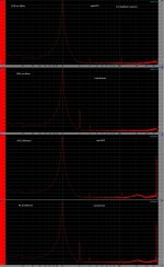
Here it is how it looked like MSB adjustment, quite some time ago, on a PCM58:
https://www.diyaudio.com/forums/digital-line-level/121552-real-fake-pcm63-12.html#post1498270
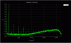
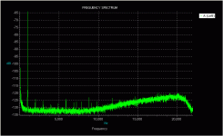
I report here, first spectra pcm58 original, second spectra the same but MSB adjusted
Here it is how it looked like MSB adjustment, quite some time ago, on a PCM58:
https://www.diyaudio.com/forums/digital-line-level/121552-real-fake-pcm63-12.html#post1498270
I report here, first spectra pcm58 original, second spectra the same but MSB adjusted
Attachments
I see, distortion is then hidden in the noise floor, a proper equipment is needed 😀 ... you should see under -120dB as Joseph posted
Laser,
Here it is how it looked like MSB adjustment, quite some time ago, on a PCM58:
https://www.diyaudio.com/forums/digital-line-level/121552-real-fake-pcm63-12.html#post1498270
I report here, first spectra pcm58 original, second spectra the same but MSB adjusted
Yeah, looks like this ADC is not gonna be accurate enough to make any meaningful adjustment
you can do a blind test ... turn the trimmer just with a music and hear a difference 😀
if there is one, find what you like the most and keep it 😀 if you don't find any, leave it default and you can set it up in the future 🙂 ... trust your ears 😀
if there is one, find what you like the most and keep it 😀 if you don't find any, leave it default and you can set it up in the future 🙂 ... trust your ears 😀
Interesting. Does your FFT software allow you to increase the number of 'bins'? - that will decrease the noise.
Cant see any option for it.
With the trimmer installed now it has no effect on the THD, so the ADC is still distorting more than the DAC, oh well
With the trimmer installed now it has no effect on the THD, so the ADC is still distorting more than the DAC, oh well
No wait..
The ADC do not have any idea about the input..
If it had a flat (understand: distortion spurious free) noise floor before, then everything must originate in the Dac..
What is tha step? From what I/V resistor to the 5kohm?
Are You using an opamp I/V? (Hope very much..)
If it is passive I/V then this is what destroys the Dac performance..
Ciao, George
And.. the excitation signal.. how did You prepare it?
How many bits? Did You apply dither? Be careful because dithering / noise shaping can help to lower the test signal noise floor but also is eliminating, smoothing out the Dac (DUT) distortion components..
In fact more tests would be needed. One with 'enhancing' dac distortions, and then one with a proper software upsampling, with the right, proper amount and type of dithering applied, which then smoothens out the residual dac harmonics..
This way maybe One do not even need MSB trim..
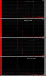
To illustrate, would report again from that old thread
https://www.diyaudio.com/forums/digital-line-level/121552-real-fake-pcm63-12.html#post1498258
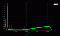
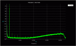
The first graph is without dither, the second is with dither applied on a PCM63:
https://www.diyaudio.com/forums/digital-line-level/121552-real-fake-pcm63-12.html#post1498258
The first graph is without dither, the second is with dither applied on a PCM63:
Attachments
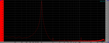
Last note: in the graphs there it is always that rising noise floor, it's because we tried all this with CD players, 16bit. So it was needed the test signal dithered down to the 20 bit level, applying noise shaping in the audio range.
This is the rise observable. It had been prepared by Pedja at the time.
Ciao, G
This is the rise observable. It had been prepared by Pedja at the time.
Ciao, G
you can do a blind test ... turn the trimmer just with a music and hear a difference 😀
if there is one, find what you like the most and keep it 😀 if you don't find any, leave it default and you can set it up in the future 🙂 ... trust your ears 😀
😀.... I like it... really ! 🙂
by ear, i tried turn fully clockwise and anti clockwise, no different, i haven't any instrument to adjust it....... hahaha
No wait..
The ADC do not have any idea about the input..
If it had a flat (understand: distortion spurious free) noise floor before, then everything must originate in the Dac..
What is tha step? From what I/V resistor to the 5kohm?
Are You using an opamp I/V? (Hope very much..)
If it is passive I/V then this is what destroys the Dac performance..
Ciao, George
At the time I checked compared to another DAC (the PC's motherboard DAC) with same input level to the ADC and the distortion looked very similar, but double checking I see PC's DAC distortion remains the same even when the level increased... the distortion is not coming from the ADC
I did some more measurements, changing many different variables to try to get a clearer picture, with some interesting results.
These were all with -5dB signal instead of -60dB, as im more interested in the IV and more blatant distortions.
It appears my op amp IV is distorting with higher feedback resistors, even 2.5k, which is lower than AD1862's internal resistor.
passive resistor or trafo IV adds considerable 2nd order HD but not much else, trafo reduces it a bit compared to just a resistor
Attachments
- Home
- Source & Line
- Digital Line Level
- DAC AD1862: Almost THT, I2S input, NOS, R-2R
