maybe the osci board have external rows free to permitt to stack the whole yet ?Thanks, guys, I ll try to remove it. It came together with an oscillator board, maybe this is why.
read the datasheet, maybe there is a gnd pin on the same I2S pins row then you will just need a standalone row for the miro1360's board. And powersupply could come fromoutside too ?

Dremel circular saw is your friend 🙂 (for the miro's board not for the transistor... re read my post)It is a problem. oscillator board prevents adding a bigger heatsink there
with a good soldering iron you can desolder little by little the pins as per miro description. Flux help as a good desoldering pump, sometimes you have to add more solder in order al the via is hot enough and there is mass enough for the desoldering pump. Gnd vias are harder of course because it is harder to heat of course...
Edit : there are header at Audiophonics in order to avoid a minimal fees at Mouser (but at Mouser you can find good op amps... and crystek XO to g a little further than NDK)
Last edited:
look first how is made the osci board, I see two double row on it
Attachments

If anyone can give mouser codes for headers so I have them equispaced and at the correct pitch I would be very grateful.
Some stuff is not worth buying from Mouser, unless in a hurry.
https://www.aliexpress.com/w/wholes...?spm=a2g0o.home.auto_suggest.1.650c76dbpwrjrD
https://www.ebay.co.uk/itm/31556613...aV1Cg3-Rh-&var=&widget_ver=artemis&media=COPY
Or I can send you some
Or I can send you some
Thanks, Jom but I will have them ordered from Mouser together with other stuffOr I can send you some
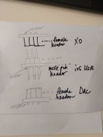
The 3 boards ( XO board, i2s XO board and DAC board) can only be stacked using 2.54mm header pins that are long, perhaps 50mm types .
You can snip away excess length of the pins if necessary. Sorry for the ugly drawing. Not sure of the height clearance between boards. The black plastic spacer is actually adjustable by pushing it along the pins carefully. But you may want to explore this way.
You can snip away excess length of the pins if necessary. Sorry for the ugly drawing. Not sure of the height clearance between boards. The black plastic spacer is actually adjustable by pushing it along the pins carefully. But you may want to explore this way.
Attachments
I have nver bought such items from mouser but an example would be this :Thanks, Jom but I will have them ordered from Mouser together with other stuff
https://www.mouser.sg/ProductDetail/TE-Connectivity/9-146277-0?qs=g1eCW3XhYQJJ1hNVICHcwA==
You can explore which pin lengths and number of pins to get from here. They are breakeable to your desired number of pins in a row.
It feels more comfortable to change to a larger one to manage some of the heat. I doubt JLSounds would use a heatsink that is inadequate. However, one can also drop the input voltage for this part (USB section) to 3.9V as specified in the user guide. That would also remove some heat.It is a problem. oscillator board prevents adding a bigger heatsink there
Dremel, knives and cuts....hmmmmm .... this stack is designed beautifully ....would be a waste.
Ultimately, if one is unable to find a solution to the physical stacking of the 3 boards.. then i guess it would be simply stacking of the XO and i2soverUSB board.... and then wiring out of the duplicate rows of pads from the XO board to the DAC inputs.
Below pic shows how a member here did it......hope he does not mind i post a snap shot here:

Below pic shows how a member here did it......hope he does not mind i post a snap shot here:
Q:
I want order a custom-made toroid. I need 2x9v for the USB and clock and 15+-v for the IV stage.
Should I go for a single toroid with 4 windings or it is better to have 2 separate ones?
I want order a custom-made toroid. I need 2x9v for the USB and clock and 15+-v for the IV stage.
Should I go for a single toroid with 4 windings or it is better to have 2 separate ones?
You might want to consider an R-Core instead of a torroid. They can be purchased easily from Ebay with various lower voltages.
If your Mico DAC build becomes a journey rather than a destination, as it seems to be for many of us, then ordering a custom transformer would be premature... There are so many tweaks to try and configurations to explore. So much so it seems I have started a collection of R-core transformers 😉
I wish I had time to play like that. I am about to commit to a PhD so for the next 5 years I'll listen to what I built. 🙂
- Home
- Source & Line
- Digital Line Level
- DAC AD1862: Almost THT, I2S input, NOS, R-2R