Thanks Miro. So for instance if I have say 10 cm wires between the PSU2 and your board, better to keep both the 0,1 mkp and a low esr lythic (higher capacitance than 220 uF you mean?)
What I like in the PSU1 is the idea of the large cap that act more as a rapid reservoir cap for the load, reg here only to feed constant this output cap while the load see mainly this cap that is faster than a reg... I would improve it till 10 000 uF. However to muc low esr make the the 7xxx family reg not so good... they like more high esr, old used cap 220 uF to avoid the serie resistor for staying low impedance....so not 0,1 mkt or mkp uF at the output of the board but only on the dac board near the load.
However indeed I see the LT reg of the PSU2 like low esr cap at their output reading on the datasheet, I do not understand why there is this instability on the PSU2 that ask a 2R2 cap ? Too big local reservoir cap just before the regs ? Should be a little less uF than the follower cap after the reg ? Or at least the cap before the reg should be lkwer esr than the output one but frol an equal capacitance ?
Btw I have a question please, in the CRC of the PSU2, may I use solething a liitle higher in R or should it stays as low ? I have ssveral boards so I will use ghem in other projects.
I also lurked on the denoiser of Elvee thread, and a gentleman just acheveid and given gerbers to the communauty, many thanks to him, lm317, lm 337 based, small, cheap parts...though for the analog side only (not for the clock or the dac chip) but very good for the analog, solething between psu 1 and 2 but nearer to the psu2 than the 1 for performances. -30 to -50 db less noise and psrr and dht than a lm317...
@gaszto, fifopi and jlsounds differ...the fifo has the advantage from the...fifo. it is also very dependant on how you power both despite they are isolated. If you feed the jlsounds with a Rpi from its usb then better to buy a low cost of the Rpi4 for its improved separated usb bus. However for the fifopi a simple rpi3 or less is enough.
Last edited:
I had 2R7 on hand, so I used those. I'll take a look at the noise level after I get all the other changes made. I'm adding an Amanero board, piggyback, to my front end also.
BTW, The gentleman in the Elvee thread, Trileru, is working on a no-noiser with cap multiplier, the sims are VERY good.
BTW, The gentleman in the Elvee thread, Trileru, is working on a no-noiser with cap multiplier, the sims are VERY good.
Do you have a link to that?BTW, The gentleman in the Elvee thread, Trileru, is working on a no-noiser with cap multiplier, the sims are VERY good.
@diyiggy 10cm is "far away" from the chip 🙂 Regulators without capacitor are meant to be as close to the chip as possible - each DAC chip should have its own regulator ... these capacitors also reduce cross-talk.
LDO regulators can be used with low-esr capacitors on the output but only up to certain capacity. Big capacity (let say 1000uF) can create oscillation. When you look at the DAC, the sum of the parallel capacitors is quite large. This does not apply only to the PSU-2, but also to other LDO regulators.
CRC of the PSU-2 ... you can go with little higher in R, like 2R2 😁
@Vunce
I have no experience with the no-noiser. I do know Trileru found that some transistors required a small inductor in series with the output cap in the de/dienoiser and also found that in the no-noiser in sim. We will have to wait and see what Trileru comes up with after he builds a couple.
I have no experience with the no-noiser. I do know Trileru found that some transistors required a small inductor in series with the output cap in the de/dienoiser and also found that in the no-noiser in sim. We will have to wait and see what Trileru comes up with after he builds a couple.


What is adding the no noiser vs the denoizer and die-nolzer for analog circuitry ? The dienoizer seems the good trade off for analog not sure you hear a difference for the best with the no-noiser ? And anyway it is for retrofit around lm317, I link it asit seems a good trade off for the 12v analog on the cheap side for those having a reg already for the digital side. While it is always the same story , does the 12v of the ad1862 being analog or fully digital ? Sole can also putt the denoiser, simplier shematic in front of their 12V... but as noticed Mjro1360, the ad1862 chip as some pkwer noise cancellation at its voltage pins ?
Of course, I asked more for the board with the output cap populated.@diyiggy 10cm is "far away" from the chip 🙂 Regulators without capacitor are meant to be as close to the chip as possible - each DAC chip should have its own regulator ... these capacitors also reduce cross-talk.
LDO regulators can be used with low-esr capacitors on the output but only up to certain capacity. Big capacity (let say 1000uF) can create oscillation. When you look at the DAC, the sum of the parallel capacitors is quite large. This does not apply only to the PSU-2, but also to other LDO regulators.
CRC of the PSU-2 ... you can go with little higher in R, like 2R2 😁
Anyway for the 75xx family reg even belolw 1000 uF the cap with higher esr for me sounds better on the oaps...at least in the old cd players... putt a silmic 2 after this reg it sounds bad, putt an old used normql basic caps it sounds better...lower impedance. For the few using those regs yet. Imo the psu1 should not have this 0,1 uf cap...but easy to try with or without.
Ah thanks so not so higher as I wanted...10R...ahaha...that just because I had some good carbon resistor on hands...lol.
Last edited:
That said RC serie after a full bridge works well.... me has a trouble with the big chocks, they are good but so expensive, bulky, heavy AND veryyyyh expensive with low dcr... zatis not green....
zatis not green....pfffff, Yageo has less and less stock on Mouser, one certainly do not want to populate with Dale RN55 (that sound like carbon without the advantages of carbon)... ah Vishay...still good 🙂
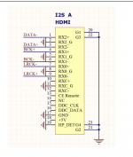
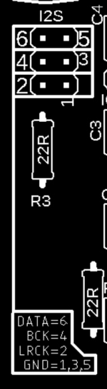
Hi everyone – I've finished up my 1862 board (rev 1.3) and PSU (v2). Super excited, as its my first endeavor into DAC/Digital DIY. Everything powers up and is looking great, but I'm not getting any sound. A few voltage checks at the dac and opamp suggest power is being supplied as intended. My main suspicion is the i2S source. I'm using a Denafrips Hermes and taking i2S (HDMI) from it to the Miro Dac (HDMI). I've attached a screenshot showing the pinout Denafrips includes in their documentation. Based on that, here's how I have it wired up:
DENAFRIPS --> Miro 1.3
3 --> 6 (DATA)
2 --> 5 (G)
4 --> 4 (BCK)
5 --> 3 (G)
9 --> 2 (LRCK)
8 --> 1 (G)
Does this wiring scheme seem correct at face value? Are there any other variables I need to consider when using the Hermes DDC? I'm happy to upload build photo tmrw to see if there's any flaw in the construction, but in my mind the signal configuration is the flashing red light.
Here's the link to Hermes documentation: https://www.denafrips.com/_files/ugd/4b933e_21e3eb20da334988acb98b834004efd3.pdf
Any help is appreciated! Don't assume any serious knowledge on my part when it comes to I2S and digital connectivity 🙂
Attachments
@codyt The wiring seems correct.
I did not find the information in Hermes documentation, about the I2S frame size (how many BCK counts are in one LRCK cycle)? 🤔 ... for my DAC it should be 64 (2 channels per 32 bits in one sample),
rare converters have 48 (2 channels per 24 bits in one sample) .... in that case you would have to adjust the DAC a bit 🙂
Do you have a digital scope or something to see the output from denafrips?
Hey Miro – thanks for taking a look! I woke up bright and early, determined to get it figured it out. I removed the HDMI connection entirely, as I'd noticed the Hermes also provided a RJ45 I2S connection. I just completed the wiring for that and its making music!! I've got about 60 seconds of listening completed, but it sounds awesome so far!
Really, really great boards btw!
Really, really great boards btw!
Awesome Cody!! Get ready to fall deep into the rabbit hole 😂
We need porn pics of your build.
We need porn pics of your build.
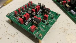
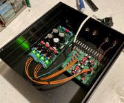
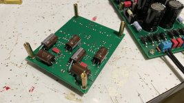
Thanks! It went together perfectly, aside from the hdmi hiccup. I haven’t finalized a chassis or layout yet, but here are a few pics in the meantime. I took your advice on undermount caps. Using TL071 right now, and have LM6171 to swap in later. Plus some discrete IV adventures in my future 🙂
PS. Big, big thanks to Keetesyflush for the free boards!
PS. Big, big thanks to Keetesyflush for the free boards!
Attachments
Last edited:
Hi,
Imo, your LM oap socket is too far from the pcb...not good for such very fast video oap. C31 in the bottom, class 2 smd cap...are they really needed ???
Try to turn the pcb in the cabinet to make the i2s input wires as short as pkssible from the source.
All the rest is very clean, kuddos for a first build 🙂
Thanks! I had a similar thought about the opamp standoff. My goal was to get the sockets high enough so I could experiment with discrete options (and didn't want to put everything on the bottom side). To be completely honest, I'm kind of using this as the 'experimentation' build. When I settle on final I/V, I2S input, chassis, etc, I'll most likely either build another board or redo portions of this and build a dedicated chassis. Regarding C31, I just followed the schematic I had. If I can do without, or if there are other wise cap, R, etc modifications, I'm definitely wiling to give them a try!
Last edited:
- Home
- Source & Line
- Digital Line Level
- DAC AD1862: Almost THT, I2S input, NOS, R-2R