yes very lately after we talk. I made first the error because the marking with the two first bjt despite you advertised me, lthen eft it few months after some problems, then completed it later. Sounds more than good, different from my reference but hard to compare as my ref diy dac has a complex digital front end and clock and had 3 years of work, on passive parts and multiples supplies ! Stock, although yours sounded better than my stock ref tda1541A S1. I see you also use R-core traffos as I did and it is one of the little trick that sounds good with this dac chip... I surmise yours onthe photo are old Selectronic with the screen wirered to the main ?
Thanks again for the two boards you sent me back then. If you want to try Miro's for the curiosity I can send you some boards I have left.
here people
Right. I don't mean to hijack this thread in anyway, I'm just curious.
Did I send you the previous version with the non-smd output stage? I think I remember that there was an error there on the boards, which marked the transistors in the wrong direction.
I think maybe the AD1862 is inherently better than the TDA1541, so it's an unfair comparison. It would be interesting to test the AD1862 with a different discreet I/V stage.
I would love to test miro's boards for comparison. If you have a couple boards left you can pm me about it.
I don't remeber how I wired the trafos. I am guessing that I left the screens floating. My memory isn't very good these days.
Yes that was the latest through hole of your thread with the marking errror on the two first bjt. Drop me your postal adress in pm, I should have time next week to send you.
Hmm, maybe trying out the trimming stage should be next experiments... thanks for the information!
Last edited:
I think I was a little inaccurate in my description. You can either use a scope and feed your dac with a -60dB sine signal and trim until you see the least amount of noise on your output. Or you canhook up your speakers and feed your dac with a very low input digital signal, while putting the volume of your amp to max, and you'll hear audible noise. And then you just trim until the noise goes away. I have done this many times. I have 110dB sensitive speakers, and the noise is really audible. I think maybe diyhifi is down now, but that's where I learnt this back in the day, and I have repeated this procedure several times.Hmm, maybe trying out the trimming stage should be next experiments... thanks for the information!
@Painkiller - any chance you would have a written procedure on how to do it?
Displaying my ignorance here, but how do you make the -60db file for the source? Exactly what do you look for on the scope? For example if the -60db is a 1khz sine, do you adjust until that 1khz is gone or is it something else?
Its a question that has come up a few times, and in truth, I've always had more basic things to fix first!

RE setting the trimmers for minimum distortion.
I use a S/PDIF Digital Audio Signal Generator.
It was a Siliconchip project from quite a few years ago.
https://core-electronics.com.au/s-pdif-digital-audio-signal-generator-kit.htmlI set it for 1k hz and adjust the level to -60dB.
Then look at the output with a scope.
The sign wave has a sort of cross over distortion & as you adjust the the trimmer you can zero it out
until you have a clean looking sign wave.
I will post some before and after scope shots tomorrow.
Last edited:
Finally I could finish the DAC.
I appreciate to Miro,Meanie,Garcia and ppl here.
I use to use Topping D70 using XLR connect.
Now I concentrate on music and more enjoy the siund more than before.
I appreciate to Miro,Meanie,Garcia and ppl here.
I use to use Topping D70 using XLR connect.
Now I concentrate on music and more enjoy the siund more than before.
Attachments
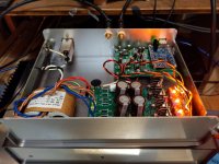
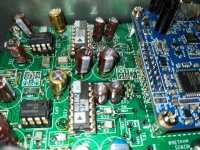
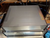
It is sad that Takachi UC series discontinued.
The chaiss is fine looking and more than enough,costs only 70usd.
The chaiss is fine looking and more than enough,costs only 70usd.

Hi guys!
My amplifier has balanced inputs.
Is it a good idea to add a non-balanced2balanced plate to the dac to make the output balanced?
My amplifier has balanced inputs.
Is it a good idea to add a non-balanced2balanced plate to the dac to make the output balanced?
@Paddy Garcia can you drop links to where you got those euvl CM IV boards? I can't find the project, it's making me feel like a goofball
Also I would love to see scope photos of someone adjusting their -60db 1khz signal for MSB. I have all the parts for this feature but haven't done it yet.
Also I would love to see scope photos of someone adjusting their -60db 1khz signal for MSB. I have all the parts for this feature but haven't done it yet.
Those were from here: https://www.diyaudio.com/community/...urrent-mirror-iv-converter-a-la-ad844.373227/
@Ripster did a tremendous service by matching transistors!
@Ripster did a tremendous service by matching transistors!
Miro,
May I ask in your AD1865 design why you connected SJR to VOutR and SJL to VOutL? What is the benefit of this solution compared to the another, where SJR and SJL connected to AGND?
May I ask in your AD1865 design why you connected SJR to VOutR and SJL to VOutL? What is the benefit of this solution compared to the another, where SJR and SJL connected to AGND?
Hi, I decided to give this DAC a go, got the DAC chips from Paddy and ordered the parts up, however I'm unable to upload the Gerbers for the I2S/USB board not flipped from post 2546 to JLCPCB, my go to PCB fab.
PSU1 uploads fine as does the board with the shift registers but not the one that I want,
Anyone else encountered this?
Andy
PSU1 uploads fine as does the board with the shift registers but not the one that I want,
Anyone else encountered this?
Andy
I had the same issue, seemed like the render function on JLCPCB did not work. Had to manually input the size and skip the render and it worked.Hi, I decided to give this DAC a go, got the DAC chips from Paddy and ordered the parts up, however I'm unable to upload the Gerbers for the I2S/USB board not flipped from post 2546 to JLCPCB, my go to PCB fab.
PSU1 uploads fine as does the board with the shift registers but not the one that I want,
Anyone else encountered this?
Andy
- Home
- Source & Line
- Digital Line Level
- DAC AD1862: Almost THT, I2S input, NOS, R-2R