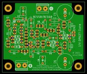
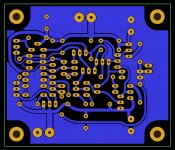
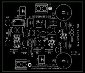
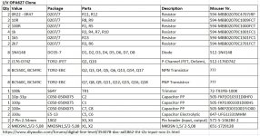
I/V OPA627 Clone
Today something different 🙂
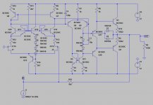
It is cloned I/V from simplified schematic in texas instruments OPA627 datasheet.
LTspice simulation worked for me - it is difficult to say whether it will work in reality
The simulation is done with BC550/560 transistors -- similiar pin-compatible transistors should work. The output transistors can be paralleled for more power.
The feedback resistor is included (therefore it is necessary to disconnect the one on the PCB - if installed).
The necessary power supply is +-12V (not less).
I don't know what more to write about it, maybe just good luck because I didn't test it 😀
Today something different 🙂
It is cloned I/V from simplified schematic in texas instruments OPA627 datasheet.
LTspice simulation worked for me - it is difficult to say whether it will work in reality
The simulation is done with BC550/560 transistors -- similiar pin-compatible transistors should work. The output transistors can be paralleled for more power.
The feedback resistor is included (therefore it is necessary to disconnect the one on the PCB - if installed).
The necessary power supply is +-12V (not less).
I don't know what more to write about it, maybe just good luck because I didn't test it 😀
Attachments
-
diyAudio_IV-OPA627-Clone_BC_2021-06-12.zip331.4 KB · Views: 188
-
 diyAudio_IV-OPA627-Clone_BC_Schematic.jpg335.2 KB · Views: 797
 -
 diyAudio_IV-OPA627-Clone_BC_Top.jpg283.9 KB · Views: 769
 -
 diyAudio_IV-OPA627-Clone_BC_Bottom.jpg194.3 KB · Views: 690
 -
 diyAudio_IV-OPA627-Clone_BC_Parts.jpg145.5 KB · Views: 628
 -
 diyAudio_IV-OPA627-Clone_BC_BOM.jpg224.1 KB · Views: 660
 -
 diyAudio_IV-OPA627-Clone_BC_Schematic-ltspice.jpg145.8 KB · Views: 516

Hi miro - you could try with an SE classA output stage instead of the 'traditional' classAB. Opamps have to use classAB because the opamp needs to cope with all kinds of output load, but here you know the output load - or you can specify it. So you can optimize - the big advantage of SE classA is that there's no variation in PSU current draw vs signal. PSU noise goes away, at least to first order.
Ernst - glad you like the PhiDAC sound! I'm working on a new version of PhiDAC right now. I found one big weakness of that design is that its rather noisy, partly because AD8017 isn't really a quiet opamp although it looks so on paper.
Btw Guglielmo has tried out one of my filters on his PCM1704 DAC and liked the SQ.
Last edited:
Here you go 🙂
PS: I reply on Monday or Tuesday (2 days off)
PS: I reply on Monday or Tuesday (2 days off)
Attachments
Last edited:
Oh good, I'll take my time a bit then. Thanks. 🙂
I took a look at the JFETs and found they're quite a bit noisier than those in OPA627 - the noise corner is rather a lot higher in frequency. So for example the 1kHz noise density is about 8nV whereas with the opamp only 5.6nV. Getting good noise data on FETs isn't particularly easy - the InterFET parts on Mouser just headline a number without any indication where the noise corner is. Makes me think they've something to hide.
I took a look at the JFETs and found they're quite a bit noisier than those in OPA627 - the noise corner is rather a lot higher in frequency. So for example the 1kHz noise density is about 8nV whereas with the opamp only 5.6nV. Getting good noise data on FETs isn't particularly easy - the InterFET parts on Mouser just headline a number without any indication where the noise corner is. Makes me think they've something to hide.
> I took a look at the JFETs and found they're quite a bit noisier than those in OPA627
It is well know that the J17x PJFETs are much noisier than the 2SJ74s.
There is nothing active that comes close.
The easy way round is to inverse polarity and use 2SK209.
And you can do the rest also in SMD.
See :
One Last Attempt at Discrete Opamp in DIP8 Footprint
Patrick
It is well know that the J17x PJFETs are much noisier than the 2SJ74s.
There is nothing active that comes close.
The easy way round is to inverse polarity and use 2SK209.
And you can do the rest also in SMD.
See :
One Last Attempt at Discrete Opamp in DIP8 Footprint
Patrick
Nice - I would change the OPS though to use a P-chan follower and CCS pull-up. That way the draw from the +ve supply is constant.
Ernst - glad you like the PhiDAC sound! I'm working on a new version of PhiDAC right now. I found one big weakness of that design is that its rather noisy, partly because AD8017 isn't really a quiet opamp although it looks so on paper.
Btw Guglielmo has tried out one of my filters on his PCM1704 DAC and liked the SQ.
Richard, yes, I like most parts of how it sounds in my chain. These parts are important for my ears and let me tolerate other flaws. Stage, highs and clean Pianos are on my virtual priority list, and at some point if time I'll order a then current version.
And yes again, I thought about asking you for a filter for the AD1862 DAC as well. Will do so in short, after having done some research.
If a filter is the way to go or me - I will see.
Cheers, Ernst
Last edited:
> I would change the OPS though to use a P-chan follower and CCS pull-up.
> That way the draw from the +ve supply is constant.
Personally I don't sacrifice noise for constant draw of one rail.
Patrick
> That way the draw from the +ve supply is constant.
Personally I don't sacrifice noise for constant draw of one rail.
Patrick
> To me, non-constant rail draw is noise.
If your circuit has no PSRR, maybe.
Want constant current draw on both rails ?
Use fully differential circuits in pure Class A.
As XEN usually does.
Cheers,
Patrick
If your circuit has no PSRR, maybe.
Want constant current draw on both rails ?
Use fully differential circuits in pure Class A.
As XEN usually does.
Cheers,
Patrick
Each to his own.
Quite, we all have our own preference for poison.
After listening for the first time to Miro's AD1862 DAC and Richard's PhiDAC not only on headphones but on speakers, I can say the TDA1387 with a sinc filter has something special for me. I know other TDA1387 converters, but none have impressed me like Richard's. Especially the clarity, the highs and the 3D stage did it to me. Do any of you have experience with these filters and how would such a filter for the AD1862 have to look like?
Cheers, Ernst
Ernst, if you want to start, here is my recommendation. Put every electronic filter part out of your schematic - i.e. with exception of non-DAC filter specific bandwidth limitations.
Start with:
sox input.wav -b 32 -e float output.wav rate -v -L 88200 sinc -a 120 -L -21000 -t 2100
That means:
The necessary fs/2 filterbehaviour of a 44,1kHz file. With -6dB point to 21kHz and the start of the stop band to 22.05kHz where is -120dB.
Try from -120 to -170... Go extreme! Try your way! Have a look at the sox-documentation. You can also generate a graphical output of your filter-behaviour.
Important to know:
The preringing exists only at fs/2 ! If there is no signal, there is no kind of ringing. That's the key of the discussion. Forget hardware filters. Too weak in case of taps - compared to computers. Even if you do not need them. But you could.
Last edited:
OK,
I had to learn, that there are two options, sinc filters and reconstruction filters - digital and hardware filters. I think, Richard works with reconstruction filter only, and he likes most 88.2 kHz sampled signals, if I remember correctly.
Often both techiques, sinx/x and reconstr. f., are used working hand in hand.
So I'll dig into sox and will look into Richards work more in detail.
Thanks TJF for your recommendation how to start. I surely will consider it. But before this I need to start with, how to work with sox. Usually I do not like to use a computer for listening to music, (exect the pi or usb-bridge in case of USB-DAC as a streaming client) but I might need it for the initial phase. I think, Pi can use sox for i.e. upsampling, but is this an appropriate way?
Interesting point, that preringing is supposed to happen at fs/2 only.
To be followed up sometime. Thanks!
Cheers, Ernst
- Home
- Source & Line
- Digital Line Level
- DAC AD1862: Almost THT, I2S input, NOS, R-2R