🙂 I like Pan FC on Ripster's board and the polyswitch is pretty cool
I like the short I2S connection from Ernst's board
I fear it is a Surimi Burson V6 plot 😉, so what oap did Burson copied to translate itr in discrete in this V6 ? NE5534 discretes like AUdioGrande or close ? Any info ?
Panasonic FC are nice but bigger so they need to be mounted on both sides.
As for Burson V6 another member here on forums tvicol dissected and reviewed them. And suggested a mod to remove two diodes so this will be my next move.
But couldn't find any reference to any other oap design...
Good evening Miro,
In your Catherine DAC you upgrade the PSU pretty much, yet you keep the pcm2706. Is it really good enough in your eyes? Will it be the bottleneck then?
In your Catherine DAC you upgrade the PSU pretty much, yet you keep the pcm2706. Is it really good enough in your eyes? Will it be the bottleneck then?
Hi Ernest. Well it is pretty complicated with the PCM2706. The part can be avoided and any xmos board used instead. I can create xmos solution, but it is not user friendly - the chip has really tiny legs for hand soldering and the programming device is needed, along with the experience.
Only solution how to improve the PCM2706 is to use the combination PCM2706+WM8804 --- to I2S. It can reduce the jitter 10x. I don't know any other user friendly solution 🙁
Only solution how to improve the PCM2706 is to use the combination PCM2706+WM8804 --- to I2S. It can reduce the jitter 10x. I don't know any other user friendly solution 🙁
Miro, thanks and understood.
A solution might be the integration of an available lower priced xmos board.
Xmos soldering would probably be doable, but programming......
A solution might be the integration of an available lower priced xmos board.
Xmos soldering would probably be doable, but programming......
Last edited:
I thought about pins integration. But again, these boards are changing. jlsounds has new version of PCB, diyinhk is producing different versions over time, there is not stable pinout for my project 🙄 and my project will live for decades. I find myself on the  and I will
  with my R-2R fans here.
and I will with my R-2R fans here.Hey remark regarding opamp THS4031, better omit this opamp, they go to heaven fairly soon: got an huge plop on speakers when I put streamer on. Measured voltages and 2 opamps had curious -12 voltages on not used pins..
This from only 6times or so on/off cycles.
And.. my pc streaming setup sounds still better in my ears compared to AD1862 dac.
1862 is relaxed, more bass forward. I like it first but in time its dull sounding and lacking some details. Very laid back and miss room information in recordings.
Stream AirPlay to moode, searching other ways but i am fearing on the long run 1862 is not my cup of tea.
Have built other non-os stuff before and have o sort of sound in mind I hoped this Dac could give me that
I like it first but in time its dull sounding and lacking some details. Very laid back and miss room information in recordings.
Going for better power supplies will open up the sound in a big way. I went overkill with an MPAudio LT3045 ALD-HPULN PS Dual Rail 2x2,5A on each of the 5v and 12v feeds and these really opened up the sound. They are expensive but proved to me the benefits of better power to really open up the DAC.
They are easy to setup up for symmetric supply.
ALD-HPULN PS | MPAudio
Hi Tubee,
You have installed the components on Miro’s board to adjust the MSB trim, did you use a test signal and oscilloscope to adjust for lowest distortion? If not, I wonder if this could be a reason for getting your subpar listening impressions? Remove the trimpots and associated resistors and have another listen.
You have installed the components on Miro’s board to adjust the MSB trim, did you use a test signal and oscilloscope to adjust for lowest distortion? If not, I wonder if this could be a reason for getting your subpar listening impressions? Remove the trimpots and associated resistors and have another listen.
Nice spot Vunce, ... and perhaps the capacitors type, and raspberry? Try to connect jlsounds or another USB-I2S to the raspberry usb 
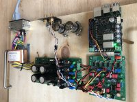
>Tubee, why not take the I2S from the reclocker and not from the pass trough GPIO header (I2S of the Rpi not reclocked by the hat) ? Even you wires are not the same length.
I would try from the uf-l socket and sacrifice 3 uf-l cable at one side for the purpose. while the gnd conexion should ask tricky diy, hence the uf-L good needs. The I2S of the Pi is FGPA abstracted from a single crystal on the Rpi so it could be a problem in relation to that or the I2S choice in the playback streamer software.
Are thz output dc blocking caps that are not bipolar on the photograph are the good direction ?
Last edited:
Iggy, I think the lines come from the isolated gpios, yet difficult to spot, and it seems the cables are 4 inch all.
Clocks are simple ones I guess, but I have no idea, if this is important for AD1862.
Clocks are simple ones I guess, but I have no idea, if this is important for AD1862.
RPI has quite high jitter with internal clocks (much higher than PCM2706)
Raspberry Pi I2S output working | Crazy Audio
Using external USB-I2S device (like xmos) could improve the sound (I have not tested, @Ripster tested it here: https://www.diyaudio.com/forums/dig...862-tht-i2s-input-nos-2r-138.html#post6490317 )
Raspberry Pi I2S output working | Crazy Audio
Using external USB-I2S device (like xmos) could improve the sound (I have not tested, @Ripster tested it here: https://www.diyaudio.com/forums/dig...862-tht-i2s-input-nos-2r-138.html#post6490317 )
Thanks for reply 🙂
Solved problem with the ths opamps, fitted the opamp feedback c0g caps on underside of pcb, Pushed some vw beetle ne5534 opamps in and to my surprise it’s sounding more decent now.
I think those ths opamps where oscillating as hell..
The I2S wires are same lengths, these are until the ufl wires will arrive with a trimpot and opa627 opamps
A low impedance PS is an idea indeed. But I know this one is fine already
Also want better accusilicon cristals in time, and a tube or tranny I/v schematic
Those tubes are not connected
Msb adjustment is not done indeed i will do this procedure
AFAIK there is no output cap @ opamp.
Are those 1 to 10 value caps coupling caps? (C15-c25 and c26-c26) then I will swap a tantalium on underside for Panasonic aluminum
Last edited:
Thanks for reply 🙂
Solved problem with the ths opamps, fitted the opamp feedback c0g caps on underside of pcb, Pushed some vw beetle ne5534 opamps in and to my surprise it’s sounding more decent now.
I think those ths opamps where oscillating as hell..
The I2S wires are same lengths, these are until the ufl wires will arrive with a trimpot and opa627 opamps
A low impedance PS is an idea indeed. But I know this one is fine already
Also want better accusilicon cristals in time, and a tube or tranny I/v schematic
Those tubes are not connected
AFAIK there is no output cap @ opamp.
Are those 1 to 10 value caps coupling caps? (C15-c25 and c26-c26) then I will swap a tantalium on underside for Panasonic aluminum
- Home
- Source & Line
- Digital Line Level
- DAC AD1862: Almost THT, I2S input, NOS, R-2R