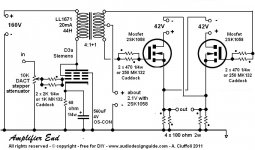
Hi all ...... after several years of just reading, here is my first post. I have recently built Andrea Ciuffoli's D3a-Mosfet circlotron amp. I would love to know if anyone on this forum has tried this design, and if anyone can help me tame its excessively bright highs without using a brutal low pass filter ?
Attachments

put load across secondary , to linearize >xformer feeding gates while leaning on bias net < mechanismus
dunno - for start put 100K trimmer across secondary , as variable resistor , and start loading it down
sweep at 1W , from 20-20K , while observing output at scope , will help you see what's happening , and to find proper loading
check that you didn't , accidentally, missed somewhere that proper anti-paralel orientation of resistors
Last edited:
Thats a strange way to connect the supressor grid, can you explain why you have chosen to do it this way?
..... help me tame its excessively bright highs ....
you mean like in, 'theres is no bass' 😕
wrong phase of Interstage ?
You must measure the frequency response to verify whether or not that is the cause of the excessive high frequency tonal balance. As indicated by a previous comment, perhaps, it's the low frequencies being 'rolled off' that is making the highs sound raised.
What method are you using to remove D.C. offset at the outputs? A too short D.C. servo time constant, or too small an output coupling capacitor could possibly be the problem should you find the low frequency response to measure poorly.
If the frequency response measure sufficiently flat and extended, then the perception of elevated or overly aggressive sounding high frequencies could conceivably be caused by excessive distortion, or even oscillatory behavior.
put load across secondary , to linearize >xformer feeding gates while leaning on bias net < mechanismus...
Yes, I would agree this is what is needed.
Right now the gain is proportional to the inductance of the drive transformer's loading of the drive tube.
There is some loading at higher frequencies due to the FET's input capacitance but not much.
Decide what load line the tube should be operating at and calculate through the transformer what the secondary load should be.
I would also clamp the FET's gates to prevent overvoltage. This is one limitations of FETs that should not be ignored.
Vgs max on data sheet.
Happy listening.
Very specific recommendations:
[1] Pentode cathode resistor 68 ohms, change to 220 ohms.
[2] Bypass pentode plate transformer primary with 47K, 1 watt resistor in parallel with primary. Carbon composition is just fine for this purpose.
Theory behind #1: every possibility that transformer is running close to saturation. Drop amperes through it, without substantially changing gain. Should have significant effect if hypothesis is correct.
Theory behind #2: inductive load becomes high enough to emphasize transients. Providing a simple resistive "knee" in the response curve gives pentode a real non-transformative load to chew on. May well, by itself, solve problem. Suggestion above to use a 100K pot is good. Be careful - at lower ohm settings, may burn out due to excessive power dissipation. You can put a 15K resistor in series with it, to prevent, but the 15K needs to be 5 watt.
I have a third and fourth suggestion, but they're less likely, and require more difficult wiring changes on the output MOSFETs. By the way - the output mosfets at 2.1 volts may be significantly over-biased. This can cause HF clipping, as they are not particularly linear MOSFETS.
Good luck.
GoatGuy
...By the way - the output mosfets at 2.1 volts may be significantly over-biased. This can cause HF clipping, as they are not particularly linear MOSFETS.
Good luck.
GoatGuy
????
not understanding here.
MOSFETs are in source follower mode.
🙂
I'd like to thank all of you guys for all the advice. This is a truly great forum.
Tinitus : no the bass is phenomenal. I've never heard anything like it from all the tube SETs I've built.
Ken : I will try measuring frequency responce (kind of a newbie) however I cannot see any oscillation at any frequency.
DUG : can you explain how I clamp the gates ?
Goatguy : wow that's quite specific (thanks). I will try your suggestions now. Incidentally, I have tried shunting the secondaries with variable R. All the way down to 600 ohms. Very little audible difference.
Ken, the DC offset is removed by actually having separate bias trimmers for each mosfet. Unlike the schematic the interstage secondaries are separate.
Very specific recommendations:
[1] Pentode cathode resistor 68 ohms, change to 220 ohms.
[2] Bypass pentode plate transformer primary with 47K, 1 watt resistor in parallel with primary. Carbon composition is just fine for this purpose.
Theory behind #1: every possibility that transformer is running close to saturation. Drop amperes through it, without substantially changing gain. Should have significant effect if hypothesis is correct.
Theory behind #2: inductive load becomes high enough to emphasize transients. Providing a simple resistive "knee" in the response curve gives pentode a real non-transformative load to chew on. May well, by itself, solve problem. Suggestion above to use a 100K pot is good. Be careful - at lower ohm settings, may burn out due to excessive power dissipation. You can put a 15K resistor in series with it, to prevent, but the 15K needs to be 5 watt.
I have a third and fourth suggestion, but they're less likely, and require more difficult wiring changes on the output MOSFETs. By the way - the output mosfets at 2.1 volts may be significantly over-biased. This can cause HF clipping, as they are not particularly linear MOSFETS.
Good luck.
Hi GoatGuy, tried both your suggestions, and I hate to say this : no audible difference. So ........ what are your 3rd and 4th ideas ?? Having said which, the amp sounds extraordinary and I really appreciate your help.
- Status
- Not open for further replies.
- Home
- Amplifiers
- Tubes / Valves
- D3a - MOSFET HYBRID CIRCLOTRON