Friends I need help, I'm already a few days ago with this amplifier can not find the problem..
The problem is with the D3a tube, not give me enough amplification, with 1V peak-to-peak (1 kHz) at input give me 2.5V to the output.
The anode voltage is 190V (10k resistor load) and the cathode is 2.1 V with a resistance of 104ohms (20mA aprox). Filament 6.6V.
In one tube G2 is connected to the anode and g3 to ground and on the other channel g3 to cathode and g2 to anode, in both channel I have the same result.
The tubes test good in my Eico 667 tube tester (95%)
Any idea?
Hi!
The output voltage you get from a specific input signal depends on the step down ratio of your output transformer. Since you did not specify that, it is difficult to tell whats going on.
Measure the gain of the D3a stage alone and then go from there.
Best regards
Thomas
The output voltage you get from a specific input signal depends on the step down ratio of your output transformer. Since you did not specify that, it is difficult to tell whats going on.
Measure the gain of the D3a stage alone and then go from there.
Best regards
Thomas
1.You can connect baypass cap about 500-1000 uFto every cathode resistor. 2.Try to connect in pentode mode /g2 conn. to res. about 50 kohm to B+, g2 conn. to electr. cap about 50 uF to ground/.....and look.
Last edited:
Hi Azazello,
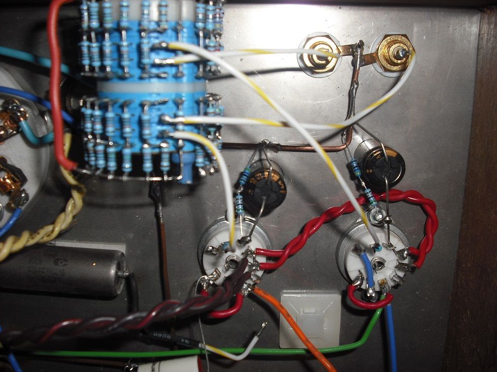
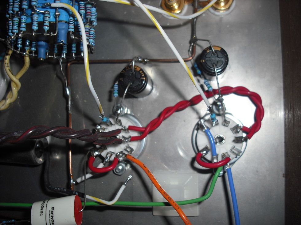
when looking at the photos, there seem to by bypass caps at the cathodes.
Before changing the configuration of the tube, I would strongly suggest to first check if it is working correctly. He then still can change it if the gain is not sufficient
Best regards
Thomas
when looking at the photos, there seem to by bypass caps at the cathodes.
Before changing the configuration of the tube, I would strongly suggest to first check if it is working correctly. He then still can change it if the gain is not sufficient
Best regards
Thomas
Have you measured that the 1V signal is also at the grid of D3a not only at the input connector ?
You have some fault in the circuit. Try to find that.
Do not change to other topology (pentode), because this is not the solution.
Can you post the circuit diagram ?
You have some fault in the circuit. Try to find that.
Do not change to other topology (pentode), because this is not the solution.
Can you post the circuit diagram ?
Thank you all for reply!
Sorry for be unclear, the measurement is in open circuit, I put a 100k resistor to gnd for measure the output voltage (anode-cap-resistor to gnd). Please see the picture.
The cathode is bypass with 220uf cap, maybe low value?
The voltage signal (1V) is measured in the 1k grid stopper resistor.
Now, time to sleep for me, more to come..
Hi.
You should post the schematic.
You should also put a stopper resistor between G2 and the anode.
There is a problem somewhere, you can't get only 2.5 gain - I get 70 with a CCS loaded D3a...
And dont't you feel sorry for your expensive NOS D3a to kill them slowly with the 6.6v heater?
You should post the schematic.
You should also put a stopper resistor between G2 and the anode.
There is a problem somewhere, you can't get only 2.5 gain - I get 70 with a CCS loaded D3a...
And dont't you feel sorry for your expensive NOS D3a to kill them slowly with the 6.6v heater?
Hi!
So you are measuring 1V in and 2.5V out of the driver? Then there is definitely something wrong. Where did you measure the output voltage?
Best regards
Thomas
So you are measuring 1V in and 2.5V out of the driver? Then there is definitely something wrong. Where did you measure the output voltage?
Best regards
Thomas
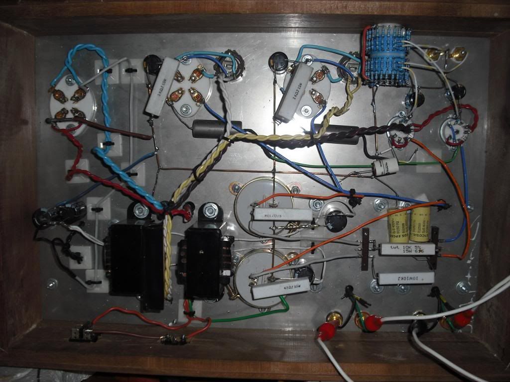
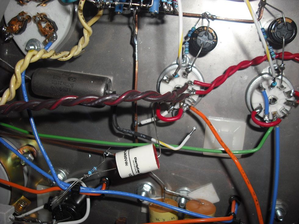
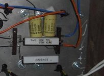
Hi! These two yellow caps in the first picture, right above the 10k resistor. It is my impression they are connected to the 'wrong' side of the plate resistors. They are probably meant for decoupling of DC supply, but it looks as if they have been connected to the anode side of the 10k resistor. This could explain why you are not getting gain. Still, the picture is not very clear.
Other things: are you sure the 100k resistor after cap is indeed 100k (and not 100R)?
These may sound silly suggestions, but I made/make these sort of errors myself as well.
General observations regarding layout. The D3a as high transconductance valve is said to oscillate at the minimum chance. I saw you used grid stoppers, which is good, but I don't know if placing the plate resistors so far and connecting them with wires to the plates is a good practice. And as Vincent said, some care around G2 as well. These are probably not the reasons for getting low gain, but may be reasons for future problems, especially oscillation.
Best regards, Erik
Attachments
Last edited:
Problem Solved!!
Thanks to all for reply!
Erik you have good eye!!!
The whole problem is because the wrong conection of these yellow caps 😱
Now is time to improve the layout and put again the g2 grid stopper.
Thank again!
Alberto.
Thanks to all for reply!
Erik you have good eye!!!
The whole problem is because the wrong conection of these yellow caps 😱
Now is time to improve the layout and put again the g2 grid stopper.
Thank again!
Alberto.
Hello Alberto,
you should also consider the usage of a anode stopper (22-47R) with such long leads to the anode resistor and coupling cap. Also the usage of ferrite beads on g1, g2, anode and cathode is highly recommeded with a tube like the D3a. To make things even better you can connect a 1nF ceramic cap from the each heater pin to the chassis.
Best regards,
Martin
Hi Alberto!
great that you can move ahead now. I would really consider the recommendations given by the other members, like the precautions against oscillation and reducing the heater voltage on the D3a.
saludos Brasileños de Moçambique! Erik
great that you can move ahead now. I would really consider the recommendations given by the other members, like the precautions against oscillation and reducing the heater voltage on the D3a.
saludos Brasileños de Moçambique! Erik
Ceramic resistors in cathode of 300B is not good idea. You can try to change to Mills resistors- 12 W and sound will be really great. Mills resistors page
Better You can use shunt el. caps Black Gate , Elna,
Better You can use shunt el. caps Black Gate , Elna,
Hello,
By the way, the best way to get a solid rock operating point of the D3a is to follow the datasheet by using a positive grid voltage (about 10V) and a higher value cathode resistor. But this requires a coupling cap between input and grid.
Best regards,
Martin
Of course, you shouldn´t use them if the heaters between 300B and D3a are shared. Only if the D3a has its own heater.Ceramic resistors in cathode of 300B is not good idea.
By the way, the best way to get a solid rock operating point of the D3a is to follow the datasheet by using a positive grid voltage (about 10V) and a higher value cathode resistor. But this requires a coupling cap between input and grid.
Best regards,
Martin
Last edited:
- Status
- Not open for further replies.
- Home
- Amplifiers
- Tubes / Valves
- D3a-300b amp help!