Since I have mentioned it a few times already I suppose I do. Can you please math it out to how much it would drift IF Iadj changes? Datasheet mentions by how much. Please explain by how much it changes at what Vout. Because you seem to be on some fearmongering quest on this project and I don't properly understand your motivation, but I have a few guesses.
You also keep asking redundant questions which have already been addressed.
And for the nth time, 1.2K is a datasheet value as maximum recommended value. Brave of you to go against a datasheet value.
You also keep asking redundant questions which have already been addressed.
And for the nth time, 1.2K is a datasheet value as maximum recommended value. Brave of you to go against a datasheet value.
I will not "maths it out" for you.
Do not give to me: Intentions, i do not have.
I only gave here, design informations.
Do not give to me: Intentions, i do not have.
I only gave here, design informations.
Did not care to read 3000+ posts and 5 years of debating (sorry) but are there positive and negative definitive stable versions ready to build?

Tne Show Must Go On....
I think it's a kind of clinical addiction .🤔
I think it's a kind of clinical addiction .🤔
Yes there are: have a look at the index of the first post, Mark's VRDN project for examplebut are there positive and negative definitive stable versions ready to build?
I got all the parts to test this version but yet to order the final PCBs. It includes the latest developments and is Denoisator based, no NoNoiser for this. If you use the correct parts (like any other circuit) it should be stable.


I'm hoping for around 2W TDP per rail, with the small heatsinks.
I'm hoping for around 2W TDP per rail, with the small heatsinks.
Thank you, hadn't noticed an index was made. Five years is a long time 🙂 Very practical in the jungle of versions.Yes there are: have a look at the index of the first post, Mark's VRDN project for example
But I am not planning to read/interprete/try all the stuff in the index as it will possibly take another 5 years to evaluate. Relevant question to me therefor is:
- which version performs simply better than LT3045/LT3094 without practical undesired issues?
In other words: which one is it worth to build for practical use in an +/- 15V opamp circuit with about 100 mA maximum current draw? The VRDN? And which brand of LM317/337 to use?
Last edited:
From last measurement Denoisator with CCS and R1=3.3K bests LT30_whatever at PSRR and noise in audio spectrum. Simulation also shows lower output impedance as well.
Found an interesting LM317 version, it's called LM317L from TI:
https://www.ti.com/product/LM317L
Datasheet: https://www.ti.com/lit/gpn/lm317l
It's a 100mA version, in TO-92 and SOIC packages, and some other SMD one. Other than that it seems to have an interesting graph in the datasheet.

That seems like a very small variation, 0.2-0.3uA between 25C-75C. And some of the example applications use R1=470R. Other datasheets don't use such a high value, they stick to 120-240R. This could be interesting for low power and high R1, though I wouldn't go past 3.3K there isn't much performance to be gained past that value.
Other than that I think the LM317-N is the higher PSRR version, still from TI.
https://www.ti.com/product/LM317-N
And there's one more interesting one, though it doesn't contain the Iadj graph, and could be a mix of the two, it's called LM317L-N, and its description states it's also a high-PSRR version. This could be pretty nice if it does have low Iadj variation. Still TO-92 version, 100mA max.
https://www.ti.com/product/LM317L-N
Though LM317L-N still has the classical 0.2uA typical/5uA max Iadj drift in the table specs (and confusingly enough so does LM317L, even if it has the low drift graph, table specs are the regular LM317 ones for Iadj drift). So I'm not sure the L version is low Iadj drift or not, as a general rule.

This shows about 2uA drift, for LM317L-N. But most R1 in datasheet applications are 240R, apart from the max recommended one of 1.2K, it pops up in this datasheet as well.

https://www.ti.com/product/LM317L
Datasheet: https://www.ti.com/lit/gpn/lm317l
It's a 100mA version, in TO-92 and SOIC packages, and some other SMD one. Other than that it seems to have an interesting graph in the datasheet.
That seems like a very small variation, 0.2-0.3uA between 25C-75C. And some of the example applications use R1=470R. Other datasheets don't use such a high value, they stick to 120-240R. This could be interesting for low power and high R1, though I wouldn't go past 3.3K there isn't much performance to be gained past that value.
Other than that I think the LM317-N is the higher PSRR version, still from TI.
https://www.ti.com/product/LM317-N
And there's one more interesting one, though it doesn't contain the Iadj graph, and could be a mix of the two, it's called LM317L-N, and its description states it's also a high-PSRR version. This could be pretty nice if it does have low Iadj variation. Still TO-92 version, 100mA max.
https://www.ti.com/product/LM317L-N
Though LM317L-N still has the classical 0.2uA typical/5uA max Iadj drift in the table specs (and confusingly enough so does LM317L, even if it has the low drift graph, table specs are the regular LM317 ones for Iadj drift). So I'm not sure the L version is low Iadj drift or not, as a general rule.
This shows about 2uA drift, for LM317L-N. But most R1 in datasheet applications are 240R, apart from the max recommended one of 1.2K, it pops up in this datasheet as well.
Without numbers that is a weak argument on your behalf.I will not "maths it out" for you.
Do not give to me: Intentions, i do not have.
I only gave here, design informations.
Connect an LED + current limiting resistor between the regulated output and ground. Select the resistor such that 11 milliamps flows through the LED. Now the regulator is very happy (even when the PSU is not connected to the load (during assembly and debug)) and you can choose the VOUT-to-ADJ resistor's value however you wish.
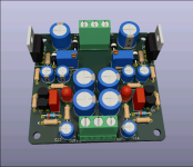
I did make a refresh of the THT design but I'd have to test it first, contains the CCS BJT and startup spike filter, for Denoisator topology. It's also DIY-able.
Can the trimpot be replaced with a fixed value resistor?
Last edited:
From what I see in the assembled pcb on you are still using trimpots for the final adjustment.

Isn't there a version that doesn't need those?
Not to take away from Diego's post but I ran some AC measurements for the Denoisator with R1=3.3K, both LM317 and LM337. And performance is phenomenal!
One thing I was curious about was testing varying Vce values for denoiser and strangely enough it doesn't seem to matter, 3V or 9V noise and PSRR is the same. This makes things simpler, you can set Vce of denoiser BJT to some half Vout and it'll be fine. This also means you can use any LED color for CCS, IR to UV if you want.
Another advantage of having a lower Vce is lower startup spike. Vce at 6-7V with the filter makes for virtually no...
Isn't there a version that doesn't need those?
I combined testing LM337 addon board on the old NoNoiser THT design from this post with nothing installed but input/output caps and regulator. And R1/R2, 2.7K/22K, makes for some 12Vout.


I sensed the noise right at output connector, and ran the ADJ wire next to regulator. LM337 made by ST and marked LM337SP
Addon board had these values installed:

Was made before I got the MMBTA06/56 so I ran with what was already installed, BC807-25 for denoiser BJT. 10uF caps because I couldn't easily find 5mm 22uF ones, in my stash.
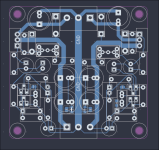
PCB has similar output trace/output capacitor location design to the latest version which is attached to this post.
PSRR came out a bit weaker, 123dB at 105Hz but I had R1=2.7K so there's a bit of loss there, compared to R1=3.3K.

Noise (and maybe a bit of PSRR) was also a bit worse as I had the 33R protection resistor installed (forgot to add it in previous photo), and it contributes 104nV on top of rest of noise.

So total noise would be around 260nV without the 33R resistor. Previous measurements with MMBTA56 came out at some 180nV.
Tested some 20-30 output capacitors and it was stable with most of them. Anything 150-250mR was fine. 47uF was too low, but 100uF-470uF was fine.
Anything that ESR meter showed as 0R, basically too low to measure, 30-50mR range, wasn't stable. I used a 200mR resistor, if connected through it they worked, as long as they were at least 100uF.
So I don't know what to say about output caps. One other detail that might matter is Vdrop across regulator, because of my battery setup I had some 4V across the regulator. Don't know how much that matters. If you have issues with LM337 Denoisator oscillating try having at least 4V across the regulator, at least test it if you can. Have at least 100uF/200mR or higher output cap, one was enough for me.
I also made this testing session while looking at AC.
@carlmart I put the potentiometer in parallel with two other resistors, which can be mounted instead of it:

Left side where it says RV1, there's two resistors instead. They are in series with another resistor, you can tweak Vout very fine or just short the series resistor.
LM337 denoiser BJT has RC compensation, the R is both THT (R21) and SMD on the backside (R11), 0805. Gives more options for the 3.6-3.9R value needed. Cap is THT only, maybe use a ceramic cap.
R18/R22 is ESR correction resistor, only 0805. Short JP1 and JP2 to bypass them if you have correct ESR output caps.
JP3/JP4 normally open for CCS version. Omit Q3 and Q4 and short JP3/JP4 if you want classic Denoisator topology. You can still keep the LEDs but they're status LEDs only with classic Denoisator (JP3/JP4 closed). Don't install Q3/Q4 if you short these jumpers.
Second set of output caps are not needed but may help with lowering ESR or increasing capacitance.
This board isn't tested but somewhat tested (general layout), so use it at your own risk, at least until I get to order/make one and populate and test it.
Attached ZIP file has Kicad project files, gerbers, PDF for schematic and PDF for DIY PCB.
edit: do note that BJTs are BC3x7 pinout. For MPSAx6 you need to rotate them 180 degrees (I think).
I sensed the noise right at output connector, and ran the ADJ wire next to regulator. LM337 made by ST and marked LM337SP
Addon board had these values installed:
Was made before I got the MMBTA06/56 so I ran with what was already installed, BC807-25 for denoiser BJT. 10uF caps because I couldn't easily find 5mm 22uF ones, in my stash.
PCB has similar output trace/output capacitor location design to the latest version which is attached to this post.
PSRR came out a bit weaker, 123dB at 105Hz but I had R1=2.7K so there's a bit of loss there, compared to R1=3.3K.
Noise (and maybe a bit of PSRR) was also a bit worse as I had the 33R protection resistor installed (forgot to add it in previous photo), and it contributes 104nV on top of rest of noise.
So total noise would be around 260nV without the 33R resistor. Previous measurements with MMBTA56 came out at some 180nV.
Tested some 20-30 output capacitors and it was stable with most of them. Anything 150-250mR was fine. 47uF was too low, but 100uF-470uF was fine.
Anything that ESR meter showed as 0R, basically too low to measure, 30-50mR range, wasn't stable. I used a 200mR resistor, if connected through it they worked, as long as they were at least 100uF.
So I don't know what to say about output caps. One other detail that might matter is Vdrop across regulator, because of my battery setup I had some 4V across the regulator. Don't know how much that matters. If you have issues with LM337 Denoisator oscillating try having at least 4V across the regulator, at least test it if you can. Have at least 100uF/200mR or higher output cap, one was enough for me.
I also made this testing session while looking at AC.
@carlmart I put the potentiometer in parallel with two other resistors, which can be mounted instead of it:
Left side where it says RV1, there's two resistors instead. They are in series with another resistor, you can tweak Vout very fine or just short the series resistor.
LM337 denoiser BJT has RC compensation, the R is both THT (R21) and SMD on the backside (R11), 0805. Gives more options for the 3.6-3.9R value needed. Cap is THT only, maybe use a ceramic cap.
R18/R22 is ESR correction resistor, only 0805. Short JP1 and JP2 to bypass them if you have correct ESR output caps.
JP3/JP4 normally open for CCS version. Omit Q3 and Q4 and short JP3/JP4 if you want classic Denoisator topology. You can still keep the LEDs but they're status LEDs only with classic Denoisator (JP3/JP4 closed). Don't install Q3/Q4 if you short these jumpers.
Second set of output caps are not needed but may help with lowering ESR or increasing capacitance.
This board isn't tested but somewhat tested (general layout), so use it at your own risk, at least until I get to order/make one and populate and test it.
Attached ZIP file has Kicad project files, gerbers, PDF for schematic and PDF for DIY PCB.
edit: do note that BJTs are BC3x7 pinout. For MPSAx6 you need to rotate them 180 degrees (I think).
Attachments
Last edited:
That's a SMD test board I made. I usually install a trimpot footprint that can be used with resistors instead, if you really hate trimpots. Same with THT as I explained in previous post.From what I see in the assembled pcb on you are still using trimpots for the final adjustment.
Not to take away from Diego's post but I ran some AC measurements for the Denoisator with R1=3.3K, both LM317 and LM337. And performance is phenomenal!
One thing I was curious about was testing varying Vce values for denoiser and strangely enough it doesn't seem to matter, 3V or 9V noise and PSRR is the same. This makes things simpler, you can set Vce of denoiser BJT to some half Vout and it'll be fine. This also means you can use any LED color for CCS, IR to UV if you want.
Another advantage of having a lower Vce is lower startup spike. Vce at 6-7V with the filter makes for virtually no...
Isn't there a version that doesn't need those?
- Home
- Amplifiers
- Power Supplies
- D-Noizator: a magic active noise canceller to retrofit & upgrade any 317-based VReg