Which is the CCS Denoisator?The original Denoisator was always stable with LM317. There are some issues with LM337. But I am using the CCS Denoisator atm in my headphone amp and works fine both LM317 and LM337.
CCS NoNoiser is a bit harder to keep stable, output capacitor network is more important, a bit of extra inductance is needed to keep LM337 stable.
DC-coupled LM317 was also stable, I can't remember LM337 or even if I ever measured it.
The regular Denoisator or CCS Denoisator should be the biggest improvement in PSRR and noise floor and output impedance while keeping LM3x7 tempco.
Have you tried an assembly of any of those 7X15 fixed voltage regulators Diego had suggested?Forgot to mention, if you ever have issues with LM337 stability just remove the output cap's ground leg and add some 3cm of 1mm diameter wire between pin and its PCB pad, should make it stable. Or whatever thickness wire you have, 0.5mm at 2.5cm, something that should give you some 20-25nH.
Has anyone tried them?
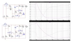
I simulated on LTSpice both Diego suggestions on #3036. This what I got.
Also tried to simulate noise, but if I remember well the 317 does not include noise parameters.
I wonder what else can I simulate with both schematics. Mine includes an RC filter at the input.
Also tried to simulate noise, but if I remember well the 317 does not include noise parameters.
I wonder what else can I simulate with both schematics. Mine includes an RC filter at the input.
Attachments
I think the (LT) model does ?? "fiddling" with the currents and passives does alter the plots.317 does not include noise parameters
OS
Attachments
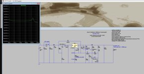
When you click on the 317, is its noise contribution displayed? In the visible traces list, is the 317 present?
Isn't the LM317 itself in the denoising loop?
@ostripper also try without R9. I also use an IR LED in the CCS, has some 1.1Vdrop, since there's around 1.25V between Vout and ADJ pins it allows to match Vce of denoiser BJT to around ADJ pin levels. That's not really possible with a red LED in the CCS, or CCS may work poorly. Some 120R for R7 makes for about 8-9mA through the denoiser BJT, with red LED. With IR LED I use 50R to result in the same 8-9mA. Also run around 1.5mA through the CCS LED.

@ostripper also try without R9. I also use an IR LED in the CCS, has some 1.1Vdrop, since there's around 1.25V between Vout and ADJ pins it allows to match Vce of denoiser BJT to around ADJ pin levels. That's not really possible with a red LED in the CCS, or CCS may work poorly. Some 120R for R7 makes for about 8-9mA through the denoiser BJT, with red LED. With IR LED I use 50R to result in the same 8-9mA. Also run around 1.5mA through the CCS LED.
Which is the CCS Denoisator?
Forgot to mention, using the CCS and setting a high Vce for denoiser BJT makes for a huge startup swing, it's really really bad. Hence why I add the diode string in my designs, bypassing the output cap of the denoiser. It limits the startup swing.
Or you could run it at low Vce like the original Denoisator, some 3-4V I think, but you might as well just use the regular Denoisator at that point, I don't think I tested the CCS with low Vce for denoiser.

For 12Vout 3x1N4148 are enough. For 5Vout one does the job. At 25Vout you need about 5 of them.
You could also use a red LED for 12Vout, only lights up for a second at startup and fades away:

Or you could run it at low Vce like the original Denoisator, some 3-4V I think, but you might as well just use the regular Denoisator at that point, I don't think I tested the CCS with low Vce for denoiser.
For 12Vout 3x1N4148 are enough. For 5Vout one does the job. At 25Vout you need about 5 of them.
You could also use a red LED for 12Vout, only lights up for a second at startup and fades away:
Last edited:
No.When you click on the 317, is its noise contribution displayed?
No.In the visible traces list, is the 317 present?
Forgot to mention, using the CCS and setting a high Vce for denoiser BJT makes for a huge startup swing, it's really really bad. Hence why I add the diode string in my designs, bypassing the output cap of the denoiser. It limits the startup swing.
Or you could run it at low Vce like the original Denoisator, some 3-4V I think, but you might as well just use the regular Denoisator at that point, I don't think I tested the CCS with low Vce for denoiser.
View attachment 1371346
For 12Vout 3x1N4148 are enough. For 5Vout one does the job. At 25Vout you need about 5 of them.
You could also use a red LED for 12Vout, only lights up for a second at startup and fades away:
View attachment 1371349
But you also have to adjust the value of R5/26, which becomes now 350K instead of 180K.
What about using a simple Red LED for D2/D6 instead of an IR LED?
I'll describe how you choose the important part values for a CCS Denoisator, which ties into your question.But you also have to adjust the value of R5/26, which becomes now 350K instead of 180K.
What about using a simple Red LED for D2/D6 instead of an IR LED?
We consider this circuit, say you have it in LTSpice or made a PCB for it:
First thing you do is disconnect C5 and adjust R2 until you get your desired Vout.
Once you set Vout you keep C5 disconnected, and choose R6 value such that around 1.5-2mA flow through the CCS LED. For 12Vout 6.8K is fine.
Once you did this you set R4 which sets the current through the Denoisator BJT. For 8-9mA with a red LED that resistor should be 120R. For an IR LED that resistor should be 50R (47R should also work fine). This nets in about 10mA total, CCS LED + Denoisator BJT, which is the minimum current draw that's recommended by LM317 datasheet, so it works out nicely this way.
Once you did all this you have to set R5 which sets Vce of Q1, which has to be in a particular small (ish) range for everything to work out nicely. Once that is set you can connect C5 and everything should work fine.
Vadj of LM317 is always 1.25V lower than Vout, that's what positive side of C5 sees. But negative side can be at most at Vout-Vdrop of CCS. Which can be at minimum Vdrop of CCS LED. So with a red LED Vce of Q1 can be at most Vout-1.7V. Which is some 0.45V lower than positive side of C5. But with only 1.7Vdrop across the CCS it won't properly work especially if we consider tempco variation.
With an IR LED, Vce of Q1 can be at Vout-1.1V, so it can be a bit higher. Which matters when we consider tempco variation of Q1.
If we run a simulation for 25C and 75C it becomes more clear
That's some 1.2V variation of Q1 Vce between 25C and 75C. Don't know which way they go when they heat up, some BJT spice models go higher Vce some go lower. Either way, you need to account for this variation.
The way I do it is set the highest headroom with an IR LED, but set Q1 Vce at about 0.6V lower than Vadj.
So about 10.10V. This way, there's around 0.8V upwards headroom until the CCS performance starts being affected, and around 1V downwards headroom until the diode string starts conducting:
If Vce goes too low the diodes start conducting and Denoisator gets DC-coupled to LM317 ADJ. This is why I use three diodes for 12Vout and IR LED for CCS, they allow for this tempco variation of Q1 without affecting the regulator performance.
You could potentially build a spice sim which looks good with red LED and only two diodes, but run it at a different temperature and you'll soon find out why it's not recommended:
Isn't this the way to check for LM317 model noise? The regular and simple LM317 application? These models result in different noise levels but one is not particularly labeled LM317Then, the 317 model does not include noise

Are the LTSpice stock models to be trusted for noise? BC817 is pretty close to ZTX851. 37nV vs 34nV, total in audio spectrum. BC337-25 is higher at about 137nV total and BC337-40 about 150nV. And I have noticed this in my tests, the fact that with BC3x7 pair the regulator has higher noise than with BC8x7.
Ideally, noise modelling requires modelling down to the component level to be completely accurate, which is labor-intensive and is generally avoided.
With an opamp, you can get away with noise voltage and current, but for other types of ICs, a more complete model is required to be accurate in all situations
With an opamp, you can get away with noise voltage and current, but for other types of ICs, a more complete model is required to be accurate in all situations
They use the basic semiconductor fundamental theory to derive the noise, and without the other contributions, all junctions behave identically: the equivalent noise resistance is ~1/2 the dynamic resistance.Are the LTSpice stock models to be trusted for noise? BC817 is pretty close to ZTX851. 37nV vs 34nV, total in audio spectrum.
Including the Rbb is not too complicated, but it is rarely accurately specified, and therefore the end result can be generic and inaccurate
Can there be performance differences between different packages for same part? I noticed there's sometimes two different spice models for same part but for two different packages.
For example MMBT2907, comes in SOT-23 as MMBT2907 and SOT-323 as MMBT2907AW, two different spice models (onsemi)
For example MMBT2907, comes in SOT-23 as MMBT2907 and SOT-323 as MMBT2907AW, two different spice models (onsemi)
- Home
- Amplifiers
- Power Supplies
- D-Noizator: a magic active noise canceller to retrofit & upgrade any 317-based VReg