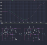
I have made a simulation, and it works as expected:

The red trace is completely flat compared to the green reference.
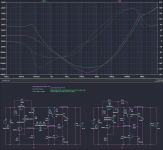
In the frequency domain, it is even more striking:

The improvement reaches almost 55dB, and with such a simple configuration, stability is guaranteed without any compensation.
The noise should be improved in the same proportions
The red trace is completely flat compared to the green reference.
In the frequency domain, it is even more striking:
The improvement reaches almost 55dB, and with such a simple configuration, stability is guaranteed without any compensation.
The noise should be improved in the same proportions
Attachments

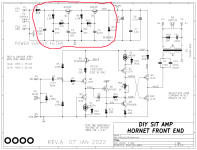
Ship Of Theseus front end cards did similar things; here's the "Hornet" from Jan 2022. If the output current is low (as it is on Hornet), stunts like R1+C1 improve PSRR even more. And "UDP3" (prefilter for Pearl3 phonostages) goes even further by inserting an inductor in series with R1, for an additional -20dB/decade of PSRR.
_
_
Attachments
That is somewhat different: it is cascading whereas Want To..'s idea is synergy, which brings some benefits: a single power device, a single voltage loss, the ability to chose a very low noise correction transistor, to name a few.
Cascading could bring a marginally better PSRR, depending on the Early voltage of the transistors, but optimization of the denoiser values would probably match it
Cascading could bring a marginally better PSRR, depending on the Early voltage of the transistors, but optimization of the denoiser values would probably match it
One important thing in this "new" discrete regulators path is that three wire transformers will be able to be used, and avoid the problems that 337 regulators seemed to have with the denoizator. Isn't it so?
Yes, it certainly is but you have to jettison the excellent static accuracy and stability of the 3xx regulators -which for audio circuits is mostly irrelevant anyway-
BTW, Trileru and myself have proposed no-compromise discrete regulators: the best of both worlds
BTW, Trileru and myself have proposed no-compromise discrete regulators: the best of both worlds
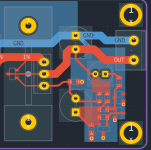
A small ground plane with the entire DeNoiser circuit, and then connect it directly to the output terminal?Don't overthink the layout more than necessary.
Start from here:
View attachment 1358819
and connect the two small arrows of the denoiser directly to the load.
There is no need for further complications. Preferably use 10nF for C2, to be on the safe side
Is it better to be the output terminal or the ground terminal of the output capacitor(C5)?
Here they are:Can you say the page your discrete regulator is in?
https://www.diyaudio.com/community/threads/discrete-regulators-with-denoiser.367721/post-6529150
https://www.diyaudio.com/community/...uperreg-with-12-discretes.331577/post-5641986
It is preferable to tie the sense connections directly to the output/load.I'm a beginner.
approach with two transistors, a small ground plane and then connect to the capacitor terminal.
is it wrong?
Ground planes bring no benefit here, since all the circuitry is very low impedance, and does not require electrostatic shielding.
They can be a dangerous thing too, since you have no idea of the actuals paths followed by the currents
This is beyond nice of you to take the time and create this for me!I have made a simulation, and it works as expected:
Could you take the schematic I sent to you and incorporate it (labels) into what you have designed?
I don't see what more I can do: I have drawn the positive side only but the negative side is the mirror image and requires no more explanation.
This is the positive side again, with the B+ label, and I cannot see how to clarify it further:

Simply graft the circuit onto your existing regulator, and it should work as expected
This is the positive side again, with the B+ label, and I cannot see how to clarify it further:
Simply graft the circuit onto your existing regulator, and it should work as expected
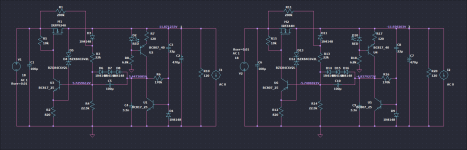
No no: Q3 and Q4 play the role of TR703 and 704, there is no need to duplicate them.
The only addition is Q5 and its associated components. C2 remains the same, but its ground side is lifted and connected to Q5.
I used 2N5550 and MJE340 because they were available in the sim, but the original transistors can be left in place.
For the negative side, you have to use opposite polarity transistors, as in the original circuit, and you have to use a BC327 for Q5 (and swap the polarities of the Ecaps and diode)
A Darlington pass transistor but 50mA load at post #2981.
The use of a compound transistor is a right way to get improved PSSR for low power regulators.
It is the usual way to go at higher power PSUs, then one gets much lower PSSR.
Just to say: Do not be mislead about the PSU power.
What are the pro and con of using a Darlington versus à Slizar for a pass regulator? How is Early voltage coming in ?
Interesting to keep in mind that NPN tend to have better Vaf than PNP.
With a unique pass bjt transistor, it is clear the dynamic resistance of the collector is: rc = Vaf / Ic
To keep things simple I use Vaf = 100V. So, for a 100mA regulator we have rc = 1000 Ohm.
With a compound pass bjt transistor, things are not that simple.
Sure, it drastically increases the dynamic resistance. I presume it only depends of the two transistors Vaf and Beta.
I am curious to know more and expect help from simulations.
The goal of my quest is to know what to look at, for a good compound bjt transistor in a pass regulator.
@mchambin
You can have a look at my version for discrete regulator with Elvee's Denoisator (with LED CCS). Should have >120dB of PSRR, and very low noise.
Works with bipolar as pass transistor but has higher output impedance. I might order a similar PCB as previous SMD LM3x7 one.
I attached the sim file though you might need the spice models
Attachments
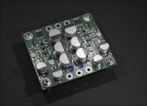
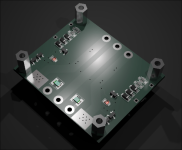
This discrete version could potentially have a DC coupled Denoisator but the startup circuit needs some adjustment. Seems to get some extra PSRR and Vout is set from R12. Less parts, higher performance, no overshoot at startup but tempco gets a hit. Sim shows some 300mV over 50C span so might work fine for some circuits.
edit: I also remembered this version of regulator "likes" 2N5551/2N5401 pair in Q1 position (2nd photo), I think I noticed it in testing as well. Are there SOT-23 versions for this pair? That's a nice boost in PSRR.
edit: I also remembered this version of regulator "likes" 2N5551/2N5401 pair in Q1 position (2nd photo), I think I noticed it in testing as well. Are there SOT-23 versions for this pair? That's a nice boost in PSRR.
Attachments
Last edited:
- Home
- Amplifiers
- Power Supplies
- D-Noizator: a magic active noise canceller to retrofit & upgrade any 317-based VReg