What are the disadvantages of using two positive regulators in series to obtain symmetrical voltages?
You will need two separate transformer windings, as a center-tapped won't work in this case.

Unfortunately, without LM337 regulator design change, it is unfixable for dienoiser version. Tried that when member kaliwraith reported issue.Dont have a scope, but according to tombo its unfixable.
Standard LM337 denoiser version works fine.
Last edited:
Thank you for your explanation.No real disadvantages, as is with connecting two separate batteries to get symmetrical supply.
It would be impossible to arrange bipolar supply on one board sharing common ground with two same regulators, but here we have two entirely separate boards and we can connect their outputs as we need. There is actually advantage that both supply rails will have exactly the same performance and transient behavior, so true symmetrical supply (if that’s important for any reason).
It makes it much easier to design a unique PCB that meets various applications, both symmetrical and asymmetrical.
Correct, but positive and negative regulators were two separate boards anyway, so two separate transformers or two separate wingdings were required.You will need two separate transformer windings, as a center-tapped won't work in this case.
Yep, that's to be expected.You will need two separate transformer windings, as a center-tapped won't work in this case.
My question is about the regulator's performance in this approach.
Performance will be better, because both regulators will perform equally well. As long as you have two secondaries available, this is the preferable way, I'd say.
@tombo56 you may still hook those two boards up to a center tapped secondary though, which would not be possible using two equal boards with just '317.
@tombo56 you may still hook those two boards up to a center tapped secondary though, which would not be possible using two equal boards with just '317.
I have no need or application for that. After denoiser, I’ve moved to super regulators.you may still hook those two boards up to a center tapped secondary
For center tapped version, there is VRDN supply project.
Post #918 version is perfectly fine.
Latest is at post #939, but no major change there, just power-on LED. As said, dienoiser version for negative supply doesn’t work.
Latest is at post #939, but no major change there, just power-on LED. As said, dienoiser version for negative supply doesn’t work.
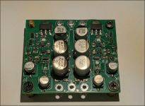
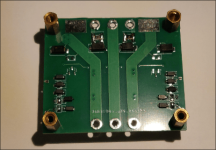
I did manage to assemble the SMD board but didn't test it with LNA. Still Vout seemed stable even when poking with metal tweezers at denoiser circuit innards.I didn't create gerbers; @Trileru did.
I hope you are talking about the regular denoiser, because the dienoiser cannot be stabilized, as Tombo said. For the regular denoiser, you can find useful tips about the suitable types of 337 in the VRDN thread.
You'll have to browse through a large number of posts, but it is worth the effort
This design should be close to 140dB for PSRR and lowest noise out of all designs, though I'll have to run the LNA tests.
Also this is for around +/-12Vout. LM337N from TI seems stable so far. Output caps are nothing special. I provisioned the board with extra 0805 footprints in series with output caps, just in case I'd need to use some small inductance there but doesn't seem necessary at least looking at DMM on output. Still, even if it proves necessary I might be able to design the extra inductance into the PCB traces, so as to remove that component altogether.
I want to also test with two BJTs in parallel in denoiser circuit for that extra low noise but I need to find the time for everything.
Attached schematic for the values I assembled on the PCB, including BJT gain ratings. I used the Nexperia spice models for BJTs and TI's LM3x7-N spice models.
Attachments
I also had a crack at negative dienoiser but it wasn't a good experience. Thought I got one stable (with addon board) but in time it started to oscillate. I had better luck with the negative NoNoiser version (with CCS)Sorry, but negative dienoiser version can’t be made stable without changing design. Positive regulator is unconditionally stable and two positive regulators can be used for a bipolar supply.
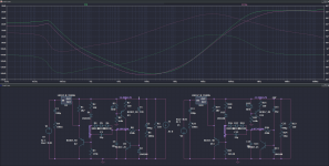
In the previous post I made a mistake in indicating the curves. The correct indication is: the green curve is with capacitor C7 (as the manufacturer usually suggests), while the red curve is without C7.
It can be seen that the circuit is quite tolerant to the presence of C7 (in the low frequency zone), so for the implementation of the "Eliminator" it would not be necessary to eliminate C7.
Only if the high frequency area needed to be significantly improved would I suggest removing C7.
Greetings

It can be seen that the circuit is quite tolerant to the presence of C7 (in the low frequency zone), so for the implementation of the "Eliminator" it would not be necessary to eliminate C7.
Only if the high frequency area needed to be significantly improved would I suggest removing C7.
Greetings
Last edited:
Because of remarks about postive rail and negative rail power supplies:
Using 2 same positive regulators, instead of, 1 positive and 1 negative.
There is a third way to do it: 1 positive regulator with a rail splitter. This way, a 30V supply becomes a +15 0 -15 supply.
I can do this, in a project where I do know there is very little current at the 0 volt provided by the rail splitter.
One can use an IC dedicated to rail splitting, but:
I use half a NE5532 wired as a voltage follower. This gives me a 0V analog ground, capable of 25mA.
I use the other half to go at chassis ground.
What do you think ?
Virtual ground ( Rail splitter ) TLE2426 Ouput current +/- 80mA.
For applications where you need +15V 0V -15V at, up to 80mA, this is a way to go with a +30V 0V that can be made based on a TL431.
Final result: -120dB Ripple rejection, rock stable regulators using about 12 parts.
Are they more powerfull virtual ground IC ? Or well proved ways to make some, with discrete parts ?
Last edited:
There is still another way of regulating split rails with two 317's: for the negative rail, you regulate GND. It looks acrobatic, but it is doable if AND ONLY IF the current drain on the negative rail is always larger than the positive one.I can do this, in a project where I do know there is very little current at the 0 volt provided by the rail splitter.
In situations where the current drain is ~symetrical (opamp circuits, etc.), you can add a bleeder on the negative output to fulfil the condition
I do not see an interest in this other way. Acrobatic, indeed.
Two 317 based regulators will be more parts than one 317 based regulator + a rail splitter.
May be, I missed something.
I had a look at Virtual ground ( aka Rail splitter ) ICs. I found nothing interesting: Found a few, but pricey for not much mA capabilities.
I think there are ways to make a simple rail splitter using discrete parts, aiming at few 100 mA capability. May be, this has already been done.
My quest is a dual voltage +V 0V -V: Low cost, easy Diy- ing, high performance, for many audio line level équipements.
Yes, this covers all the ways to make a two rails regulated PSU, avoiding the use of negative regulators.There is still another way of regulating split rails with two 317's: for the negative rail, you regulate GND. It looks acrobatic, but it is doable if AND ONLY IF the current drain on the negative rail is always larger than the positive one.
In situations where the current drain is ~symetrical (opamp circuits, etc.), you can add a bleeder on the negative output to fulfil the condition
As you said, it is pretty acrobatic, but douable.
On the other hand, I see that virtual ground ( aka Rail splitter ) is not a panacea.
It should not be used blindly, it should only be used aware of currents at the 0V.
- Home
- Amplifiers
- Power Supplies
- D-Noizator: a magic active noise canceller to retrofit & upgrade any 317-based VReg