When 35V 317 output with R4/R5 pair, collector of Q1
1K8/180K: 7.1203403V 15.4889806mA
3K8/360K: 7.057951V 7.7619512mA
9K6/960K 7.02135527V 3.8860766mA
did R4 and R5 have to be 1:100?
1K8/180K: 7.1203403V 15.4889806mA
3K8/360K: 7.057951V 7.7619512mA
9K6/960K 7.02135527V 3.8860766mA
did R4 and R5 have to be 1:100?
100 is about the good ratio, but it is not critical.
You should look at the waveform on the collector, not just the static voltage
You should look at the waveform on the collector, not just the static voltage
Thanks Elvee. Q1 collector V and I waveform look good no clipping, it seems to be able mirror the ac noise well.
Will gather parts to build it thanks.
Will gather parts to build it thanks.
Is it possible to use in series to have symmetrical PS? (transformer with separate windings)
Would there be any problem with load balancing? or something to consider?
** I saw that there is another topic that deals with the symmetrical version, but only on the positive board is the board better reused.
Would there be any problem with load balancing? or something to consider?
** I saw that there is another topic that deals with the symmetrical version, but only on the positive board is the board better reused.
You don't need separate windings: a center tap is enough, and is in fact preferable: for example, if the load on the (-) side is very light, you will lose almost half of the transformer's VA rating, because the (+) side will dictate the minimum current rating for the windings.
With a center tap, the load will always be shared equally between the two windings
With a center tap, the load will always be shared equally between the two windings
But you can use a common center tap only if you use a negative regulator, like an LM337. If you use two 317 the windings have to be separate. Isn't it?
For those that do not have access to reliable parts suppliers, that provide legitimate parts, like in Brazil where I live, the only source is China.
And LM337s are harder to find. Those available in Brazilian traditional shops now are most probably fake than legit.
And LM337s are harder to find. Those available in Brazilian traditional shops now are most probably fake than legit.
The need to make 2 boards to have a symmetrical version, if only the positive one could be used in series to have the symmetrical version, makes everything easier.For those that do not have access to reliable parts suppliers, that provide legitimate parts, like in Brazil where I live, the only source is China.
And LM337s are harder to find. Those available in Brazilian traditional shops now are most probably fake than legit.
But I don't know the real difference between not using the negative regulator, could this cause a specific problem?
Can you elaborate?if only the positive one could be used in series to have the symmetrical version,
Afaik you just need two independent transformer windings and two rectifiers.to have the symmetrical version, makes everything easier.
With separate windings from the transformer.Can you elaborate?
Exactly. But does using it this way cause any problems?Afaik you just need two independent transformer windings and two rectifiers.
Not using the negative regulator, could it harm performance?
What is most recommended? it's because?
hello all,Small BOM correction
R4 corrected to 620 Ω. With 100 Ω trimmer, regulation range should be 4,8 to 5,35 V.
i have built denoiser using tombo56 PCB V3 and using his 5V BOM.
I have a question about R1 (“10-47R “ … ”quasimodo jig determined ”)
Q: any guidance on R1 value in the range given?
What should i test for to determine the correct value ?
what does R1 do? (looks like some form of filter on the input AC?)
how critical is the value of R1?
(i did try to read thru a lot of the posts, but admittedly at 2800+ .. i might have missed some 🙂
thanks in anticpation of some guidance , much appreciated
Hi LV,
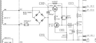
could your Dnoizator improve significantly the RevoxA77 21V supply?

this A77 case is not a LM317 one yet, but I hope it can be compared or even changed into one (the B77 has used already the LM317).
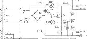
The Q101 here seems to do a few things in the feedback loop of Q102 and use its gain? Is this similar to Dnoizator effect although not so efficient?
The Hum level of the original is bothering me at ca. -70dB. My hopes are for -110dB.
Edit: I mean hum levels during Repro. Probably NAB EQ brings the hum ca +40dB up from much less values. In addition, the Repro amp should have some minimal level of PSRR too. I cannot evaluate the full situation, but I came up with this question regarding potential use for Dnoizator.
could your Dnoizator improve significantly the RevoxA77 21V supply?

this A77 case is not a LM317 one yet, but I hope it can be compared or even changed into one (the B77 has used already the LM317).
The Q101 here seems to do a few things in the feedback loop of Q102 and use its gain? Is this similar to Dnoizator effect although not so efficient?
The Hum level of the original is bothering me at ca. -70dB. My hopes are for -110dB.
Edit: I mean hum levels during Repro. Probably NAB EQ brings the hum ca +40dB up from much less values. In addition, the Repro amp should have some minimal level of PSRR too. I cannot evaluate the full situation, but I came up with this question regarding potential use for Dnoizator.
Last edited:
I found the other Revox B77 references in this thread, around post #1500.
Learned from them.
Still, the question for A77 (circuit above) remains.
Learned from them.
Still, the question for A77 (circuit above) remains.
Check the quasimodo thread for an exact answer; otherwise, stick a 22 ohm or so: it might not be optimal, but it is not critical at allQ: any guidance on R1 value in the range given?
The screenshot is too small to be legible, but the regulator is a standard two-Q regulator, of which some versions exist: look here for example, https://www.4qdtec.com/theory/2TrRegs.htmlThe Q101 here seems to do a few things in the feedback loop of Q102 and use its gain? Is this similar to Dnoizator effect although not so efficient?
A denoiser can probably added, but a redesign of the regulator is probably the first step to consider.
You could also look at Trileru's discrete regulators and my 12-parts super-reg
Thanks!
Considering to adopt a basic LM317 Reg, as B77 did after A77, I learned from posts around #1500 in this thread that Dnoizer's effect (implicitly Nonoiser's too) is rather minimal due to highly unfriendly environment and power distribution in these machines. VERY TRUE.
Hence, I guess that I need to be minimally inventive: first to find out a new power distribution for these cases.
Logically, I am considering:
a) to raise the 'dirty' 21V to 23V (10% tolerance accepted by SM) and then from it to re-regulate it locally (near boards) to 18V instead 19V. This gives available a drop of 5V, which hopefully is enough for LM317+Dnoizer to do its job correctly.
b) or to bring a shielded derivation of the 24VAC near to Repro preamp boards, and build there setup for 19V-25V (see what works best). That's probably doable as well (a bit of space is available, but size and component count still remains critical).
Harder will be to choose the correct grounding concept.
I attach screenshot again. Probably it is along the Circuit#3 in the Shootout from 4qdtec website.
Confusing for me remain many ideas in Revox. One of them is placing the Reg transistor on the Ground path. Another is the -6V node, etc..
But, again, experts tell the Revox A77 or B77 is 100% basic, check 101 EE textbook.
Okay... which book again please?

Anycase, I am keen to try to bring and test the D-noizator in this machine, because it is needed.
Considering to adopt a basic LM317 Reg, as B77 did after A77, I learned from posts around #1500 in this thread that Dnoizer's effect (implicitly Nonoiser's too) is rather minimal due to highly unfriendly environment and power distribution in these machines. VERY TRUE.
Hence, I guess that I need to be minimally inventive: first to find out a new power distribution for these cases.
Logically, I am considering:
a) to raise the 'dirty' 21V to 23V (10% tolerance accepted by SM) and then from it to re-regulate it locally (near boards) to 18V instead 19V. This gives available a drop of 5V, which hopefully is enough for LM317+Dnoizer to do its job correctly.
b) or to bring a shielded derivation of the 24VAC near to Repro preamp boards, and build there setup for 19V-25V (see what works best). That's probably doable as well (a bit of space is available, but size and component count still remains critical).
Harder will be to choose the correct grounding concept.
I attach screenshot again. Probably it is along the Circuit#3 in the Shootout from 4qdtec website.
Confusing for me remain many ideas in Revox. One of them is placing the Reg transistor on the Ground path. Another is the -6V node, etc..
But, again, experts tell the Revox A77 or B77 is 100% basic, check 101 EE textbook.
Okay... which book again please?

Anycase, I am keen to try to bring and test the D-noizator in this machine, because it is needed.
You can either rebuild the regulator from scratch with a 317 + denoiser, and you don't need extra headroom since 6V is plenty enough, or you could add a denoiser to the existing regulator.
This version should do; I just hope I made no mistake in the polarity of the E-caps and correction:

C103 should be removed, and a compensation cap might be needed across C and E of Q1, 10nF or so. This has to be tested in sim first, then refined in reality. Note that 220µ for C2 is probably overkill and it could be reduced.
All of that is to be carefully tested, of course
This version should do; I just hope I made no mistake in the polarity of the E-caps and correction:
C103 should be removed, and a compensation cap might be needed across C and E of Q1, 10nF or so. This has to be tested in sim first, then refined in reality. Note that 220µ for C2 is probably overkill and it could be reduced.
All of that is to be carefully tested, of course
- Home
- Amplifiers
- Power Supplies
- D-Noizator: a magic active noise canceller to retrofit & upgrade any 317-based VReg