A year and a half later and everything is ok. I measured it again in winter last year and was fine, nothing changed. Might do another measurement sometimes this year.Decided to test this circuit on my Magni 3 headphone amplifier (discrete current feedback amplifier). To do this I had to make two add-on boards. I broke the circuit like this:
View attachment 1080502
For this to work I had to completely remove the LM3x7 voltage setting resistors and replace the 120R-240R one (don't know the actual value Schiit used) with 2.7K. Also Cadj is gone.
View attachment 1080505
The actual add-on boards look like this:
View attachment 1080503
View attachment 1080504
And implemented on the PCB it looks like this:
View attachment 1080506
View attachment 1080507
View attachment 1080508
Not the cleanest job but I was in a hurry. Also I had to add the protection diodes which was a bit of a pain. Schiit omitted them.
I sensed the output on the 0805 100nF (removed) capacitor footprints that are in parallel with the output caps, which is a convenient place.
I set Vout at 16.7V instead of the stock 17V. Figured I leave some extra room. Output caps got replaced with 220uF for +Vout and 330uF for -Vout. These values seem to keep an acceptable startup current in the base of the denoiser BJT.
Actual used values:
View attachment 1080509
I used 2.2nF compensating capacitor and seems fine and stable.
For BJTs I chose the higher gain BC817-40 for Q6 as lower gain ones require a larger R15 and I couldn't be bothered. I don't have very high values resistors.
D21 is an IR LED with a Vdrop of around 1.1V. The bag of LEDs I took it out of had CQY99 written on it.
R14 50R value makes for around 7.5mA to the denoiser. C14 could have been 22uF for more LF PSRR performance but it would increase the turn-on surge current into Q6 base. Not by much but I decided to play it safe. This way I don't need the protection series (with C14) resistor.
To limit startup first swing I used 4x 1n4148 diodes in series and seems to work fine. On positive rail I get 17.1V max swing and on negative rail I get 16.9V. Both rails sit at around 16.7V nominal. Negative version needs around 1meg for R15 for same operating point.
Vdrop across the diode string is around 0.5V (denoiser side lower) after everything settled.
As far as performance goes it's extremely good! Here's some before and after measurements.
Positive rail before:
dBV scale
View attachment 1080510
Noise
View attachment 1080511
Positive rail after mod:
dBV scale
View attachment 1080512
Noise
View attachment 1080513
Negative rail is similar. Before:
dBV scale
View attachment 1080514
noise
View attachment 1080515
And after mod:
dbV scale
View attachment 1080516
and noise
View attachment 1080517
One mention is that measurements before were done without the denoiser half of the mod, only the NoNoiser way of setting Vout, which is similar to how a regular LM3x7 without Cadj performs. I had Cadj removed from an earlier mod and couldn't be bothered to install it for the before measurement. So stock Magni 3 might have a bit better performance than what I measured without Cadj.
I also measured the headphone output but sadly I completely forgot to ground the inputs or set the potentiometer, I have no idea of its position during these measurements. Still take it as a differential measurement before/after mod.
Noise for one of the channels before mod (low gain setting):
View attachment 1080518
And after mod:
View attachment 1080520
So even with BC8x7 for denoiser BJT performance is incredibly good. On high gain setting with the pot maxed out and I still can't hear the least bit of noise. It's dead quiet.
I have made some additional modifications to my dienoiser: the stability was very marginal for both HF and VLF.
I have changed the location of the 22nF cap, and added a 56 ohm series resistor. To improve the VLF ringing, I reduced the coupling cap to 10µF. The FR below 100Hz is relatively unimportant anyway.

I have changed the location of the 22nF cap, and added a 56 ohm series resistor. To improve the VLF ringing, I reduced the coupling cap to 10µF. The FR below 100Hz is relatively unimportant anyway.


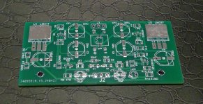
Hi.PCB V2
Here is revision of the single rail dienoiser pcb.
It now accommodates 18 mm diameter input caps. There is led indicator on the output with capacitor bypass, so it is assured that no noise will be introduced (overkill, I know). R5 resistor is moved close to output pin of LM317. Pitch for BC transistors is changed to 2,5 mm. Wonder why? I was lazy to exchange soldering tip for fine one and all pins were soldered together. That made me to replenish my curse words repertoire.
Output capacitor can be with 5 mm or 7,5 mm pitch and up to 16 mm diameter. There is position for a ESR adjusting resistor in series with output capacitor or just jumper.
If someone will build this, let me know if any help is needed with BOM list and values for specific output voltage and current.
I would like to use this circuit for 9V 500-800mA out. If I reduce R4 to 1k, will that be enough?
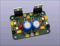
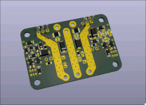
Made a board to start testing for an eventually full SMD version but didn't have time to develop it.Tango -- SMT version
Attachments
1K is OK, 1K1 would be optimalIf I reduce R4 to 1k, will that be enough?
That is one beautiful and compact board!Made a board to start testing for an eventually full SMD version but didn't have time to develop it.
Looks very nice! Can you provide the schema?Made a board to start testing for an eventually full SMD version but didn't have time to develop it.
In its present form, the denoiser is not compatible with high voltages (too much dissipation), nor with topologies more evolved than the basic 317 circuit.
However, the principles could be reused in very different applications.
Could you post the schematic of your Maida implementation? I might be able to see "low hanging fruits", and propose a simple and effective effective solution
However, the principles could be reused in very different applications.
Could you post the schematic of your Maida implementation? I might be able to see "low hanging fruits", and propose a simple and effective effective solution
Apologies for the delay.
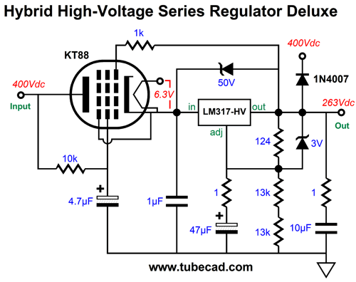
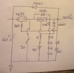
It is a version of this here....but use a 7233 series pass triode.
R1 = 200R and R2 = 48K (actually a four by 12k/4wts series string).Set for 300Vdc.
It is a version of this here....but use a 7233 series pass triode.
R1 = 200R and R2 = 48K (actually a four by 12k/4wts series string).Set for 300Vdc.
That is one beautiful and compact board!
Thank you! I might at some point. I first need to validate the design. I made a first version PCB but need to assemble and test.Looks very nice! Can you provide the schema?
I tried to add one some time ago, you'd have to drop the 263V to some low value, 15V or so, and you'd have around 2.5W (at 10mA) dissipated power in the denoiser resistor.Apologies for the delay.
It is a version of this here....but use a 7233 series pass triode.
R1 = 200R and R2 = 48K (actually a four by 12k/4wts series string).Set for 300Vdc.
I have thought about the HV version.
This is the first draft: it is based on an upside-down configuration, to increase the correction gain without increasing the dissipation. Of course, this requires a phase inversion to keep the FB negative, hence the LTP.
This is the performance of the initial circuit, with the denoiser unconnected:

The triode is a A2293, close to the 7233, and the model is created by @Adrian Immler .
I pruned all the comments and unnecessary bits to make the appearance more legible on the schematic sheet, but I acknowledge the origin and intellectual property.
Now, the situation with the denoiser active:

Clearly, an improvement.
However, the circuit is not optimal due to impedances mismatch.
To address the issue, a buffer stage can be added.
To avoid the extra consumption this would entail, the buffer can be fed from the other arm of the LTP, keeping the total consumption at ~4mA:

All of this looks promising, but it is only a preliminary work, and it has not been optimized or streamlined in any way.
In addition, many elements are lacking, even if the simulation looks alright: there is no frequency compensation, and more importantly, there are no protections. A number of diodes and zeners would be required to avoid frying the circuit the first time it is powered.
I will come up with a resilient, buildable circuit later. The compensation aspect will have to be tested on an actual prototype, because the sim doesn't help in this part
This is the first draft: it is based on an upside-down configuration, to increase the correction gain without increasing the dissipation. Of course, this requires a phase inversion to keep the FB negative, hence the LTP.
This is the performance of the initial circuit, with the denoiser unconnected:
The triode is a A2293, close to the 7233, and the model is created by @Adrian Immler .
I pruned all the comments and unnecessary bits to make the appearance more legible on the schematic sheet, but I acknowledge the origin and intellectual property.
Now, the situation with the denoiser active:
Clearly, an improvement.
However, the circuit is not optimal due to impedances mismatch.
To address the issue, a buffer stage can be added.
To avoid the extra consumption this would entail, the buffer can be fed from the other arm of the LTP, keeping the total consumption at ~4mA:
All of this looks promising, but it is only a preliminary work, and it has not been optimized or streamlined in any way.
In addition, many elements are lacking, even if the simulation looks alright: there is no frequency compensation, and more importantly, there are no protections. A number of diodes and zeners would be required to avoid frying the circuit the first time it is powered.
I will come up with a resilient, buildable circuit later. The compensation aspect will have to be tested on an actual prototype, because the sim doesn't help in this part
Attachments
This is the ruggedized, buildable version of the simpler, -125dB@100Hz variant:

Tweaking of C1 might be necessary, and it is even possible that the circuit cannot be stabilized: mixing a maida and denoiser might be too much; only an experiment will tell. Fortunately, with a triode as auxiliary device, chances are good since the gain and transconductance are low compared to semiconductors.
Tweaking of C1 might be necessary, and it is even possible that the circuit cannot be stabilized: mixing a maida and denoiser might be too much; only an experiment will tell. Fortunately, with a triode as auxiliary device, chances are good since the gain and transconductance are low compared to semiconductors.
Attachments
- Home
- Amplifiers
- Power Supplies
- D-Noizator: a magic active noise canceller to retrofit & upgrade any 317-based VReg