A resistor between collector and base does not allow to achieve VCE below VBE. At voltages lower than VBE is where the effect of reducing overshot is observed. That's why my suggestion of how to connect the trimpot.
Yes I noticed in simulation that it does work for the original Denoisator. Would be interesting if you could measure it.
If you're going to use a potentiometer to adjust Vce then in my diode version you could also use two diodes in series. That gives you a higher voltage span in which to fit all tempco variations of Vce. It does make for a bit higher swing but not by much.
I tweaked the simulation R3 value to get the same Vdrop across the diode, 60mV for 5Vout, and predicted initial swing is pretty similar to my actual measurement:

Using two 1n4148 diodes would make for a higher swing but not by much, 5.15V instead of 5.07V. Still way better than 5.5-6V.
The diodes give you their full Vdrop of working Vce variations for an unpolarized capacitor. But it being an electrolytic you have to choose a side so you get only half Vdrop for a single diode or a diode full Vdrop for two in series.
If you choose to go with higher Vce then you'd have to account for all temperature range variations, and with higher temperature Vce goes lower, so then for 75 degrees C you'd have to go +560mV higher (towards Vout) so when it heats it doesn't reverse polarize the capacitor. And this eats into the minimum voltage across the CCS and PSRR starts to drop. Maybe doable for 5V, can't do it for 12Vout.
Also this configuration is not really safe as at higher temperature it may reverse bias that capacitor.
So then Vce lower than base of Q2/Q5 it is, and you just need to set past 0V, to account for colder days. With heat this differential gets higher until the diodes start to conduct in which case you're DC coupled to the LM317. Not horrible but tempco starts to suffer.
So then you need half a Vdrop to account for highest temperature, and for 12V I tested with soldering iron on ZTX851. I kept it uncomfortably long and highest difference I measured across the capacitor was 1.4V or something like that. That fits in a 1.7Vdrop so two red LEDs in series offer this working range for temperature extremes.
Also this way highest swing is at coldest temperature. If you turn it off while hot, and turn it back again, initial swing will be even lower then if cold starting.
For higher Vout you could use different color LEDs, maybe even blue or white. You could even mix and match them if you want to account for all temperature/gain variations.
edit: it might be possible to even find standard values for R3 that would account for all Vce variations of say a ZTX851 with a comfortable first swing at certain output votlages (5V/12V/15V etc), but this would have to be tested and I only have the one ZTX851.
If you're going to use a potentiometer to adjust Vce then in my diode version you could also use two diodes in series. That gives you a higher voltage span in which to fit all tempco variations of Vce. It does make for a bit higher swing but not by much.
I tweaked the simulation R3 value to get the same Vdrop across the diode, 60mV for 5Vout, and predicted initial swing is pretty similar to my actual measurement:
Using two 1n4148 diodes would make for a higher swing but not by much, 5.15V instead of 5.07V. Still way better than 5.5-6V.
The diodes give you their full Vdrop of working Vce variations for an unpolarized capacitor. But it being an electrolytic you have to choose a side so you get only half Vdrop for a single diode or a diode full Vdrop for two in series.
If you choose to go with higher Vce then you'd have to account for all temperature range variations, and with higher temperature Vce goes lower, so then for 75 degrees C you'd have to go +560mV higher (towards Vout) so when it heats it doesn't reverse polarize the capacitor. And this eats into the minimum voltage across the CCS and PSRR starts to drop. Maybe doable for 5V, can't do it for 12Vout.
Also this configuration is not really safe as at higher temperature it may reverse bias that capacitor.
So then Vce lower than base of Q2/Q5 it is, and you just need to set past 0V, to account for colder days. With heat this differential gets higher until the diodes start to conduct in which case you're DC coupled to the LM317. Not horrible but tempco starts to suffer.
So then you need half a Vdrop to account for highest temperature, and for 12V I tested with soldering iron on ZTX851. I kept it uncomfortably long and highest difference I measured across the capacitor was 1.4V or something like that. That fits in a 1.7Vdrop so two red LEDs in series offer this working range for temperature extremes.
Also this way highest swing is at coldest temperature. If you turn it off while hot, and turn it back again, initial swing will be even lower then if cold starting.
For higher Vout you could use different color LEDs, maybe even blue or white. You could even mix and match them if you want to account for all temperature/gain variations.
edit: it might be possible to even find standard values for R3 that would account for all Vce variations of say a ZTX851 with a comfortable first swing at certain output votlages (5V/12V/15V etc), but this would have to be tested and I only have the one ZTX851.
Last edited:
I made some DC measurements as I noticed that for 12Vout the measured swing with one LED was higher than predicted. In first measurements I measured 12.44V max with one LED, this should be lower according to simulation, around 12.12V.
2x red LED - 13V max with 3.2Vmax across while starting
1x blue LED - 12.80V with 2.48V
1x red LED + 1n4148 - 12.6V with 2.0V
3x1n4148 - 12.25V with 1.4V
6x1n4148 - 12.60V with 2.8V
1x white LED - 12.83V with 2.5V
1x green LED - 12.60V with 1.75V
My red LED has a Vdrop of 1.6V while supply is starting , while simulation red LED predicts a 1.3Vdrop so there's this difference.
So LEDs don't work exactly as in the simulation, but 1n4148 diodes seem to. Analyzing these results it becomes clear that 1n4148 diodes offer the highest voltage span for the least swing. A bit difficult to use 6 in series but if you want the lowest swing you could use them.
LEDs are still usable just not as good as predicted by simulation.
I think I also figured out why the DC coupled version "liked" high CCS LED resistors, because that LED model has a 1.7Vdrop and reducing current through the LED reduces Vdrop which allows better performance at the 1.25V across the CCS. Ideally for the DC coupled version you'd use a low Vdrop LED, like an infrared. That should make it perform even better.
Attachments

I think I also figured out why the DC coupled version "liked" high CCS LED resistors, because that LED model has a 1.7Vdrop and reducing current through the LED reduces Vdrop which allows better performance at the 1.25V across the CCS. Ideally for the DC coupled version you'd use a low Vdrop LED, like an infrared. That should make it perform even better.
The transient current of the base terminal of Q1 exceeds 260 mA in the first connection. The output voltage is very dependent on temperature: about 40 mV / °C. All depending on the transistor used. The PSRR is around 140 dB at 100 Hz.
Last edited:
I removed that limiting resistor from my measurements for some time now and never had that BJT fail. But surely this should be measured. This effect might shorten their life.
PCB designs for both versions DC and AC coupled have that resistor footprint included. It affects the PSRR/noise performance so I removed it just to see how much I can push the circuits.
From simulation it looks like you could get by with a lower value while increasing the output cap and decreasing a bit the sensing one:

And yeah tempco is not great for this DC-coupled version but performance is and also there's less parts, smaller pcb. In analog audio you might find places where you can get by with bad tempco but good PSRR/noise/output impedance.
PCB designs for both versions DC and AC coupled have that resistor footprint included. It affects the PSRR/noise performance so I removed it just to see how much I can push the circuits.
From simulation it looks like you could get by with a lower value while increasing the output cap and decreasing a bit the sensing one:
And yeah tempco is not great for this DC-coupled version but performance is and also there's less parts, smaller pcb. In analog audio you might find places where you can get by with bad tempco but good PSRR/noise/output impedance.
Last edited:
The PSRR is very high given its simplicity. It's very attractive
I have noticed a better low frequency performance, if you connect the 280K resistor (between base and collector in your latest schematics) directly taken from the output (that is, in parallel to the sensing capacitor).
👍👍👍
I have noticed a better low frequency performance, if you connect the 280K resistor (between base and collector in your latest schematics) directly taken from the output (that is, in parallel to the sensing capacitor).
👍👍👍
I see that there are many discussions related to the improvement of this source. Some of them even led to the massive degradation of stabilization parameters in favor of noise reduction, but I didn't really see measurements, but more simulations.
But the most important thing I haven't seen: real measurement of a preamplifier powered simply with LM317/LM337 compared to the same preamplifier powered with improved regulators.
Has anyone made such comparative measurements?
But the most important thing I haven't seen: real measurement of a preamplifier powered simply with LM317/LM337 compared to the same preamplifier powered with improved regulators.
Has anyone made such comparative measurements?
I posted measurements for both AC and DC coupled versions, 5Vout and 12Vout, LM317 and LM337:
https://www.diyaudio.com/community/...-317-based-v-reg.331491/page-124#post-7088659
https://www.diyaudio.com/community/...-317-based-v-reg.331491/page-124#post-7089374
https://www.diyaudio.com/community/...-317-based-v-reg.331491/page-124#post-7090109
https://www.diyaudio.com/community/...-317-based-v-reg.331491/page-123#post-7076604
Out of all versions so far these are stable with just say 3.3nF.
The PSRR is very high given its simplicity. It's very attractive
I have noticed a better low frequency performance, if you connect the 280K resistor (between base and collector in your latest schematics) directly taken from the output (that is, in parallel to the sensing capacitor).
👍👍👍
Yes it's pretty interesting. I made it after recently seeing one of your older posts:
https://www.diyaudio.com/community/...y-317-based-v-reg.331491/page-97#post-6474067
I made the PCB designs so testing preamplifiers becomes now possible. Since there's no financial incentive and I'm doing this in my free time then you'll have to wait until I get to measure something powered by the AC coupled version most probably.
Perfect! No rush, I was just curious.
I don't intend to use this kind of montage, at least not in the near future.
I don't intend to use this kind of montage, at least not in the near future.
These last two versions are pretty much overkill for most audio stuff anyway. Actually apart from my discrete design I don't think there's anything available with a lower noisefloor than any of the two latest circuits. This is still experimental and I still have to test some things out to rule out potential issues.
The original Denoisator works fine for most stuff and I happily recommend it, especially for beginners.
The original Denoisator works fine for most stuff and I happily recommend it, especially for beginners.
IIRC, there have been some reports of use somewhere. They are lost in the mass of messages. The simple denoiser has also been put to good use, and there are probably testimonies in the VRDN thread too.@Trileru I do not see the audio preamplifier powered by these supplies, only the regulators.
Anyway, not all preamps are made equal: some have an excellent PSRR, and would benefit little from an improved supply, but others (especially audiophile-oriented types) can have a zero or sometimes positive PSRR (they amplify supply disturbances).
In such instances, Trileru's improvements would make a massive difference
One final wrinkle to iron out, there might be a situation where the coupling capacitor is reverse polarized during startup, for a couple of seconds around 1-2V. This with the diode mod for higher Vout.
So I've been thinking about it and I tweaked the red LED model to have Vdrop of a IR LED, at 1.1V or so.
If we replace the CCS red LED with an IR LED we get more upwards range to set Vce of denoiser BJT. The other tweak is to use two coupling capacitors in series, back to back, and also eliminate one half of the bypass diodes. This should result in smaller swing, while not reverse polarizing the coupling capacitors.

Right side circuit has D8 as IR LED, and C10/C11 are back to back. For 12Vout we can use a single LED as we get the same usable voltage span across the capacitor. We raise Vce a bit as now it's possible due to lower Vdrop of CCS. And we also remove the second LED across the coupling capacitors. And we need to tweak the CCS resistor value to keep the same 10mA or so to the denoiser.
Size shouldn't be an issue as at 12Vout we use two 68uF caps instead of a 33uF one. At 5V we need two 220uF instead of 100uF, but these can be 6.3V rated so again, no real issue with size/space on pcb.
PSRR/noise aren't affected, at least from simulation, have to measure with real IR LED.

And here's the voltage across the two back to back capacitors at 25/50/75 degrees C:

For 5Vout we have this configuration:

Using a BAT54 Schottky diode we can get virtually no overshoot at startup, for 5Vout.
So I've been thinking about it and I tweaked the red LED model to have Vdrop of a IR LED, at 1.1V or so.
If we replace the CCS red LED with an IR LED we get more upwards range to set Vce of denoiser BJT. The other tweak is to use two coupling capacitors in series, back to back, and also eliminate one half of the bypass diodes. This should result in smaller swing, while not reverse polarizing the coupling capacitors.
Right side circuit has D8 as IR LED, and C10/C11 are back to back. For 12Vout we can use a single LED as we get the same usable voltage span across the capacitor. We raise Vce a bit as now it's possible due to lower Vdrop of CCS. And we also remove the second LED across the coupling capacitors. And we need to tweak the CCS resistor value to keep the same 10mA or so to the denoiser.
Size shouldn't be an issue as at 12Vout we use two 68uF caps instead of a 33uF one. At 5V we need two 220uF instead of 100uF, but these can be 6.3V rated so again, no real issue with size/space on pcb.
PSRR/noise aren't affected, at least from simulation, have to measure with real IR LED.
And here's the voltage across the two back to back capacitors at 25/50/75 degrees C:
For 5Vout we have this configuration:
Using a BAT54 Schottky diode we can get virtually no overshoot at startup, for 5Vout.
Last edited:
Decided to test this circuit on my Magni 3 headphone amplifier (discrete current feedback amplifier). To do this I had to make two add-on boards. I broke the circuit like this:

For this to work I had to completely remove the LM3x7 voltage setting resistors and replace the 120R-240R one (don't know the actual value Schiit used) with 2.7K. Also Cadj is gone.

The actual add-on boards look like this:


And implemented on the PCB it looks like this:


Not the cleanest job but I was in a hurry. Also I had to add the protection diodes which was a bit of a pain. Schiit omitted them.
I sensed the output on the 0805 100nF (removed) capacitor footprints that are in parallel with the output caps, which is a convenient place.
I set Vout at 16.7V instead of the stock 17V. Figured I leave some extra room. Output caps got replaced with 220uF for +Vout and 330uF for -Vout. These values seem to keep an acceptable startup current in the base of the denoiser BJT.
Actual used values:

I used 2.2nF compensating capacitor and seems fine and stable.
For BJTs I chose the higher gain BC817-40 for Q6 as lower gain ones require a larger R15 and I couldn't be bothered. I don't have very high values resistors.
D21 is an IR LED with a Vdrop of around 1.1V. The bag of LEDs I took it out of had CQY99 written on it.
R14 50R value makes for around 7.5mA to the denoiser. C14 could have been 22uF for more LF PSRR performance but it would increase the turn-on surge current into Q6 base. Not by much but I decided to play it safe. This way I don't need the protection series (with C14) resistor.
To limit startup first swing I used 4x 1n4148 diodes in series and seems to work fine. On positive rail I get 17.1V max swing and on negative rail I get 16.9V. Both rails sit at around 16.7V nominal. Negative version needs around 1meg for R15 for same operating point.
Vdrop across the diode string is around 0.5V (denoiser side lower) after everything settled.
As far as performance goes it's extremely good! Here's some before and after measurements.
Positive rail before:
dBV scale

Noise

Positive rail after mod:
dBV scale

Noise

Negative rail is similar. Before:
dBV scale

noise

And after mod:
dbV scale

and noise

One mention is that measurements before were done without the denoiser half of the mod, only the NoNoiser way of setting Vout, which is similar to how a regular LM3x7 without Cadj performs. I had Cadj removed from an earlier mod and couldn't be bothered to install it for the before measurement. So stock Magni 3 might have a bit better performance than what I measured without Cadj.
I also measured the headphone output but sadly I completely forgot to ground the inputs or set the potentiometer, I have no idea of its position during these measurements. Still take it as a differential measurement before/after mod.
Noise for one of the channels before mod (low gain setting):

And after mod:

So even with BC8x7 for denoiser BJT performance is incredibly good. On high gain setting with the pot maxed out and I still can't hear the least bit of noise. It's dead quiet.
For this to work I had to completely remove the LM3x7 voltage setting resistors and replace the 120R-240R one (don't know the actual value Schiit used) with 2.7K. Also Cadj is gone.
The actual add-on boards look like this:
And implemented on the PCB it looks like this:
Not the cleanest job but I was in a hurry. Also I had to add the protection diodes which was a bit of a pain. Schiit omitted them.
I sensed the output on the 0805 100nF (removed) capacitor footprints that are in parallel with the output caps, which is a convenient place.
I set Vout at 16.7V instead of the stock 17V. Figured I leave some extra room. Output caps got replaced with 220uF for +Vout and 330uF for -Vout. These values seem to keep an acceptable startup current in the base of the denoiser BJT.
Actual used values:
I used 2.2nF compensating capacitor and seems fine and stable.
For BJTs I chose the higher gain BC817-40 for Q6 as lower gain ones require a larger R15 and I couldn't be bothered. I don't have very high values resistors.
D21 is an IR LED with a Vdrop of around 1.1V. The bag of LEDs I took it out of had CQY99 written on it.
R14 50R value makes for around 7.5mA to the denoiser. C14 could have been 22uF for more LF PSRR performance but it would increase the turn-on surge current into Q6 base. Not by much but I decided to play it safe. This way I don't need the protection series (with C14) resistor.
To limit startup first swing I used 4x 1n4148 diodes in series and seems to work fine. On positive rail I get 17.1V max swing and on negative rail I get 16.9V. Both rails sit at around 16.7V nominal. Negative version needs around 1meg for R15 for same operating point.
Vdrop across the diode string is around 0.5V (denoiser side lower) after everything settled.
As far as performance goes it's extremely good! Here's some before and after measurements.
Positive rail before:
dBV scale
Noise
Positive rail after mod:
dBV scale
Noise
Negative rail is similar. Before:
dBV scale
noise
And after mod:
dbV scale
and noise
One mention is that measurements before were done without the denoiser half of the mod, only the NoNoiser way of setting Vout, which is similar to how a regular LM3x7 without Cadj performs. I had Cadj removed from an earlier mod and couldn't be bothered to install it for the before measurement. So stock Magni 3 might have a bit better performance than what I measured without Cadj.
I also measured the headphone output but sadly I completely forgot to ground the inputs or set the potentiometer, I have no idea of its position during these measurements. Still take it as a differential measurement before/after mod.
Noise for one of the channels before mod (low gain setting):
And after mod:
So even with BC8x7 for denoiser BJT performance is incredibly good. On high gain setting with the pot maxed out and I still can't hear the least bit of noise. It's dead quiet.
correction: denoiser side higher.Vdrop across the diode string is around 0.5V (denoiser side lower) after everything settled.
Trileru, excellent improvements to am already great design. Your contributions here need to be lauded.
I have installed the first generation of nonoiser with remote sensing as an upgrade to the regulators in my Nakamichi 582 tape deck. The sound quality using the headphone output was a significant upgrade in sound.
I believe that getting the best possible regulators gets great benefit, if implemented thoughtfully.
A request
Can you please look into the impact of latest changes in the nonoiser circuit using the ZTX transistors?
I am glad that you like it!
I have made some measurements with ZTX851 and this latest version of the circuit here:
https://www.diyaudio.com/community/...grade-any-317-based-v-reg.331491/post-7088659
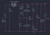
A more optimized version for 12Vout with ZTX would be this:

You could use 3x 1n4148 diodes in series across C5/C6 or a red LED. D3 should be an IR diode that has between 1-1.1Vdrop. Around 7.5mA for denoiser circuit, around 1mA for LED. With C3 at around 470uF the startup current into base of Q3 is I think acceptable. R5 should be closer to 82K in reality for 12Vout but you should test this.
For LM337 R3 might differ a bit.
I tweaked the red LED LTSpice model to have a closer Vdrop to an IR LED.
Max startup swing should be around 12.4-12.5V.
I have made some measurements with ZTX851 and this latest version of the circuit here:
https://www.diyaudio.com/community/...grade-any-317-based-v-reg.331491/post-7088659
A more optimized version for 12Vout with ZTX would be this:
You could use 3x 1n4148 diodes in series across C5/C6 or a red LED. D3 should be an IR diode that has between 1-1.1Vdrop. Around 7.5mA for denoiser circuit, around 1mA for LED. With C3 at around 470uF the startup current into base of Q3 is I think acceptable. R5 should be closer to 82K in reality for 12Vout but you should test this.
For LM337 R3 might differ a bit.
I tweaked the red LED LTSpice model to have a closer Vdrop to an IR LED.
Max startup swing should be around 12.4-12.5V.
Attachments
- Home
- Amplifiers
- Power Supplies
- D-Noizator: a magic active noise canceller to retrofit & upgrade any 317-based VReg