I do not really see what you have in mind, but it looks futile.Elvee,
Is it possible, or an absolute atrocity, to share one 3x7 with two denoisators? My feeling says it's not, but your expert opinion would better explain why.
If the Xnoisers work in //, the noise could theoretically be reduced by 3dB, but paralleling just the transistors (with a total bias current doubled) would have the same effect without the auxiliary components.
Yup, I won't be able to use the existing 3X7 boards I have and redesign them completely. I thought there might be a "loop" to the loop and somehow get away with it. It's OK.
What I have in mind is just one thing: existing space on the box I will be using and on the available space for regulators on the preamp's pcbs.I do not really see what you have in mind, but it looks futile.
If the Xnoisers work in //, the noise could theoretically be reduced by 3dB, but paralleling just the transistors (with a total bias current doubled) would have the same effect without the auxiliary components.
Do you think "share one 3x7 with two denoisators" is something that can be simulated in LTSPICE?
Well, simulate you can simulate anything. The question is what you get as a result.
Let's forget I asked anything.
Let's forget I asked anything.
That 15 ohm resistor will clobber the regulation. If load current is constant then that would not be an issue.D-Noizator: a magic active noise canceller to retrofit & upgrade any 317-based V.Reg.
✪ A simple circuit that transforms a good, clumsy workhorse like the LM317 into a superreg so easily that you do not even need to cut a single track. ✪The present SOTA in VR noise cancellation is this:
✪ It must be too good to be true.... or ✪
.........................................................................................................................
It's Christmas!!!


From Wenzel finesse regulator: Finesse Voltage Regulator Noise! |
Drawbacks are obvious:
a) Low current
b) Affects static and dynamic operation
c) Limited correction ability
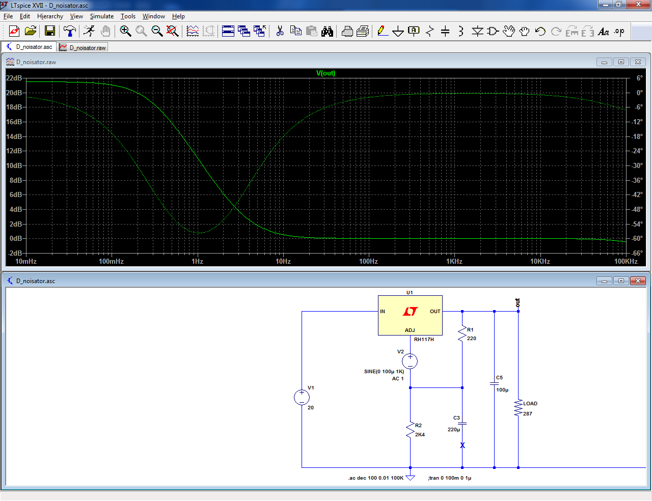
Let us start with the basic regulator (including the additional bypass cap, since we strive for the lowest noise).
An additional source symbolizing the noise is shown explicitly.
The bypass cap is effective down to ~10Hz, but the level does not fall below 0dB.
Now, let us add the D-Noizator piggy-back:
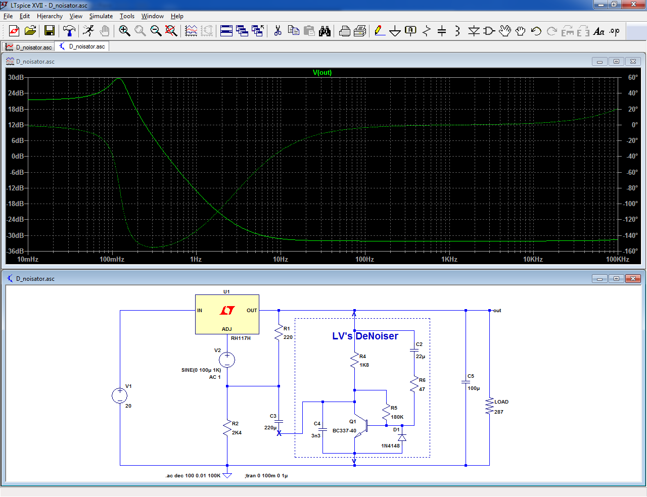
The floor drops by more than 30dB.
The circuit works by changing the output node into an AC virtual ground.
Therefore, benefits do not stop at internal noise reduction: all the performances benefit: PSRR, output impedance.
Ultimately, the performances are limited by the discrete transistor.
What about the reality?
I made a test with ST and ONsemi samples. They behave as perfect clones, both with and without the D-Noizator.
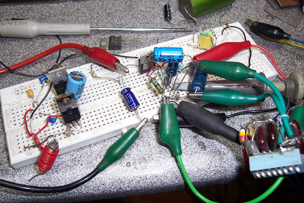
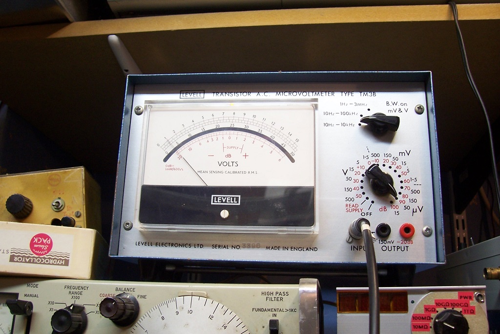
With just the cap, the noise is 16μV, as measured by a Levell TM3B.
With the D-Noizator, it falls to 2.5μV~3μV, which seems to indicate that the circuit doesnt deliver all of the promised improvement... except that the noise floor of the TM3 is also 2.5μV~3μV.
The TM3 is not a bad instrument, but it is very cheap, and very dated.
I would need to add a modern LNA to make meaningful measurements.
It is more than promising, anyway.
Of course you cannot throw a large gain into the regulator's loop without consequences: it is now forced to operate at a gain much lower than unity, and without precautions, it oscillates like mad, which comes as no surprise.
However, compensation seems to be easily achieved, and very tolerant: a capacitor larger than 2nF was sufficient to stop oscillations.
A VLF peaking is visible in the response; it could probably be polished off by increasing the splitting of the poles, or similar measures
This post details the possible versions, and provides practical information:
D-Noizator: a magic active noise canceller to retrofit & upgrade any 317-based V.Reg.
Detailed index:
Since the thread contains lots of information about various versions, sub-versions, practical implementations, etc. I have decided to gather here all of the most useful links, to help would-be builders chose the best solution for their application.
Implementions, layouts, Gerbers, etc:
These are the designs recommended by Trileru himself:
- Jack's PCB for the nonoiser in pdf form
- Sadface's Gerbers
- Hicoco's Gerbers
- Tombo56's Gerbers (tested later in the thread) and their updated versions, + negative one, and a minor correction , and BOM
- Mark's VRDN project
- A complete project, including the AC section from Iamwhoiam
- Knauf1919's Gerbers
Measurement results and comparisons:
- First, the denoiser with add-on CCS boards
- The nonoiser add-on boards
- Full size DC supply for AC-coupled Nonoiser with CCS (and lower performance variants possible)
- And the DC-coupled Denoisator with CCS
- An explanatory text by Trileru, detailing his versions of X-noisers
- Components selection guide for Trileru's designs
Miscellaneous:

Indeed. The denoiser is free from that issue and offers better overall performance for a similar level of complexity
Hi,
Is it ok to use denoiser with fixed regulator 78XX/79XX series ? Or it is definitely better to use LM3X7 and trim them to the desired value ?Thanks
Damien
Is it ok to use denoiser with fixed regulator 78XX/79XX series ? Or it is definitely better to use LM3X7 and trim them to the desired value ?Thanks
Damien
With a Dienoiser, a 78xx is usable and gives good performances: https://www.diyaudio.com/community/...grade-any-317-based-v-reg.331491/post-6022136 . It requires an additional transistor and alters very slightly the output voltage due to the injection resistor, but it should work OK
If the load current is pretty constant, then the rise in source impedance may not be a problem, and the benefit of low noise is there.Indeed. The denoiser is free from that issue and offers better overall performance for a similar level of complexity
I've been very busy, haven't been able to keep up with the topic as I'd like, so allow me a few questions.I have tested the two-transistor version.
To make it stable (in sim only, of course), I had to increase the compensation cap to 47nF, and use a very low esr 100µ output cap, but the stability looks very marginal, and the regulator model is more tolerant than its physical counterpart:
View attachment 1159600
1 - is this the last simulation attempt?
2 - at some point there was concern about stability with the LM337 for the negative rail...
Is there any problem using two boards in series to have symmetry?
As long as the input is from separate transformer windings, I believe it's ok, or i'm forgetting some important detail?
regards.
This is a sim for a "forked" version, but I don't think it has actually been tested.
For tested and proven versions, refer to the index in the first post.
The VRDN project from Mark is an example of two complementary regulators in series, and it works well (mostly). Some 337 of some origins require adjustment of the compensation components values.
The 337, even in isolation has always been more finicky than the 317: ESR of the capacitors, minimum loading current, etc
Thanks for your answer.This is a sim for a "forked" version, but I don't think it has actually been tested.
For tested and proven versions, refer to the index in the first post.
The VRDN project from Mark is an example of two complementary regulators in series, and it works well (mostly). Some 337 of some origins require adjustment of the compensation components values.
The 337, even in isolation has always been more finicky than the 317: ESR of the capacitors, minimum loading current, etc
I replicated the simulation but used TI's model for the LM317, as it seems more honest according to measurements in previous posts.
I plotted the graph together with the Super Regulator by Jung, the fight is good 😊
Super Regulator is so aggressive at subsonic frequencies, can you explain where this is relevant?
Attachments
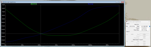
Jung's is a true DC regulator from end to end, whereas the denoiser is DC for the 317 section only, with the "super" section AC-coupled.
This makes sense for audio, because there is little to reject below 100/120Hz, but it allows greater performance where it matters most: the audio range.
The LF cutoff can easily be lowered if you fancy it: simply increase the two coupling caps to any value. It will increase the settling time though
This makes sense for audio, because there is little to reject below 100/120Hz, but it allows greater performance where it matters most: the audio range.
The LF cutoff can easily be lowered if you fancy it: simply increase the two coupling caps to any value. It will increase the settling time though
Hello all, late to the party. I would like to experiment with a DeNoiser and/or NoNoiser circuit on an existing build. The build is for a headphone amp.
The power supply I am using is a simple 317/337 followed by a cap multiplier:

I would like to try a DeNoiser or NoNoiser circuit. I like the idea very much because (1) reduced footprint size on PCB, and (2) I think would dissipate less heat. My concern is the the current I am using for the output stage.
The amp's output stage is a TO220 with a current sink set at 200mA. I've experimented with anywhere from 75mA to 200mA, and to my ears there is not much difference between 100ma and 200ma, but 200mA sounds ever so slightly better. I want to preserver that.

My question: would the DeNoiser or NoNoiser shown here here be able to handle 200mA constant current?
The power supply I am using is a simple 317/337 followed by a cap multiplier:
I would like to try a DeNoiser or NoNoiser circuit. I like the idea very much because (1) reduced footprint size on PCB, and (2) I think would dissipate less heat. My concern is the the current I am using for the output stage.
The amp's output stage is a TO220 with a current sink set at 200mA. I've experimented with anywhere from 75mA to 200mA, and to my ears there is not much difference between 100ma and 200ma, but 200mA sounds ever so slightly better. I want to preserver that.
My question: would the DeNoiser or NoNoiser shown here here be able to handle 200mA constant current?
Max available current is 1500 milliamperes IF you heatsink the LM317 appropriately. Most designers in this thread either use no capacitance multiplier at all, or else connect the CapMul before the regulator; "upstream" of the regulator. (You've got the regulator upstream of the CapMul).
The denoiser doesn't actually see the output current: the 317 or 337 does all of the heavy lifting.
Regarding dissipation, you will save the drop of the cap-multiplier, not huge.
Note that the denoiser will greatly improve the noise and output impedance compared to your existing configuration, but not the PSRR: a typical cap-mult reduces the ripple by ~60dB, give or take 10dB depending on the early effect in the transistors.
The PSRR supplement afforded by the denoiser is "only" ~30dB, but this is probably a moot point, since the ripple residues will be drowned in noise anyway.
The nonoiser or dienoiser can do better, but they are more demanding regarding compensation and stability aspects, and since a regular denoiser should be more than sufficient in your case, that's what I would recommend.
Another advantage is that it can be easily retrofitted to your existing regulators without too much hassle

Hello.
I would send the files for production in post #939. Was it modified later or is it final?
I would send the files for production in post #939. Was it modified later or is it final?
I created a combined version of tombos version but run into a slight issue. The regulator is on the same board as the headphone amp with a ground plane for both. The problem, don't know where to put the kelvin connections ground. Currently its as close as i can put it but i doubt its the most optimal spot.
Attachments
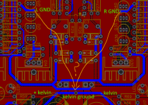
The sensing lines don't carry current so they can be thin. But most importantly they should run as close as possible to eachother to minimize the loop. In my experience sensing place is irrelevant as long as you have a clean design. In one of my earlier ADC design it didn't seem to matter where I measure the noise on the PCB, it was the same everywhere, and I did the sensing right on the output of the regulator, on the PCB. Running the sensing wires across the board might make problems worse not better.
- Home
- Amplifiers
- Power Supplies
- D-Noizator: a magic active noise canceller to retrofit & upgrade any 317-based VReg