I don’t see a reason for different startup behavior, except if that is related to the LM337. It behaves like some current limiting is in effect.
As for the noise with BC327/337, it will be very good at some 5 nV/rtHz at 15 V output or 0.7 uV total noise in the 20 Hz-20 kHz bandwidth. That are actually measured values.
As for the noise with BC327/337, it will be very good at some 5 nV/rtHz at 15 V output or 0.7 uV total noise in the 20 Hz-20 kHz bandwidth. That are actually measured values.
I did a little more experimenting. The LM337 that was in the build was a TI one, bought years ago from Farnell. I tried another one bought more recently from Mouser (also TI but with different markings) and also a 3rd one that came from Farnell several years back as well, it was a Fairchild one. All had exactly the same result, slowly ramping down to -15V over ~2-3s or so.
FYI, I also tried some 100uF/63V Elna Silmic for C8 and it also seemed to work fine (again, denoiser build). These measured 150mOhm on a de5000 at 1k. Made no difference the ramp.
My concern here is not so much noise (yes, this is important and reason why I built these) but that I have a tested and fully working build, that I didn't screw anything up! Also double checked R2, yes, it is 1r, and measured in circuit, I get close to that. All other parts check out.
One thing I haven't done is check it with different loads. Maybe I might do that next.... but I thought, is there a way to check this startup behaviour at different points on the board? If I could do that, it might at least localise it to one section.
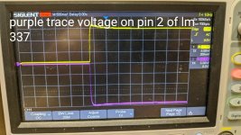
Check voltage ramp-up at LM337 input (pin 2) to be sure it is not input side problem.
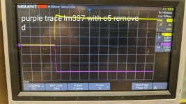
For the rest, it is hard to take meaningful measurement as all voltages are sourced from the already slowly ramping LM337 output. Next, you can remove C5 to exclude denoiser circuit influence.
For the rest, it is hard to take meaningful measurement as all voltages are sourced from the already slowly ramping LM337 output. Next, you can remove C5 to exclude denoiser circuit influence.
Try measuring the DC voltage on the collector of the BC327 (with the supply completely stable and settled)Unfortunately I don't have the tools to measure noise, something I will sort out in the future, so all I can do here is simple measurements.
Scope shots attached, but if I am correct, the slow ramp is due to the denoiser. Voltage at pin 2 with denoiser in circuit shows no ramp, and output shows no ramp when c5 is removed.
Voltage on bc327 collector pin 1:
Starts at 0V, and ramps to -5V or so over the first 10s
It then slides back down to around 2V, then back up and down but with smaller swings, and ultimately settles out at -3.4V. it takes maybe 2mins to fully settle.
During all this time the output voltage is steady.
Attachments
The denoiser Vce wobbles a bit until it settles. It's what generates the regulator's startup swing. With my swing limiter it starts DC-coupled and that limits the startup swing, especially with a higher Vce of denoiser BJT.
Ok, so all this looks normal? Output voltage has settled long before the bc327 collector voltage has settled.
Is there anything to "speed up" the output?
Is there anything to "speed up" the output?
Yes, you are correct. I’ve assembled one regulator with LM337 and checked behavior. Without C5, output voltage is at nominal value almost immediately. Increasing C5, also increases voltage rise time. Unfortunately, with 100 uF C5 value, regulator is not stable. Here is output with 220 uF C5. Nominal output is 15.3 V and there is some overshot.Scope shots attached, but if I am correct, the slow ramp is due to the denoiser.
ok, so you are seeing the same thing as me - at least now I know that there isn't something odd with my build that I couldn't see!
You can lower the value of the sensing cap or the denoiser output coupling cap. But you lose some LF performance. You have to find a balance between LF performance and startup time. How long does it take for the regulator output to stabilize, after startup? What is the value of the sensing cap?Is there anything to "speed up" the output?
It takes about 2.5s or so to reach the target voltage. The positive reg overshoots a little but is at target voltage after ~0.5-0.7s.
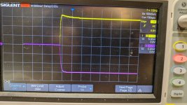
So, although it wasn't stable for @tombo56 above, I swapped in a 22uF instead of the 220uF for the coupling cap. Bingo, I see fast startup. Apart from the slight overshoot on the positive reg, both hit target voltage simultaneously, about 100ms or so I reckon.
Purple trace=negative, yellow trace=positive
Is it worth chasing the little overshoot?
Attachments
IMO, not worth at all. Most audio circuitry doesn’t care for short term supply rails asymmetry.Is it worth chasing the little overshoot?
Indeed: most circuits don't care about a transient overshoot of a few %, except maybe some microwave devices and similarly exotic devices.
The overshoot transient has been designed-in with audio circuits in mind.
It can be reduced by increasing the output cap (the large one) or decreasing the input cap (the small one). Both have drawbacks, and I think that the current tradeoff is alright, but you are free to adopt something more suitable for you
That will affect the LF performance of the denoiser. 10x reduction in value does have an impact., I swapped in a 22uF instead of the 220uF for the coupling cap. Bingo, I see fast startup.
Startup swing might affect some devices that have a max Vin limit. Like VACC of a DAC/ADC with 5V. Depends on application.
OK so maybe the final bit of experimenting now.
LM337 denoiser setup: I tried 100uF and 47uF coupling caps, both gave very similar startup times to 220uF - about 2.5s to hit target voltage. In the end, I replaced the 22uF cap for coupling and I get a time to voltage of ~170-200ms.
LM317 denoiser setup: I tried 22uF and 100uF coupling caps, and both still showed the slight overshoot, i.e. no difference to 220uF coupling, so I refitted the 220uF.
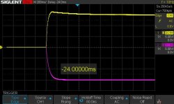
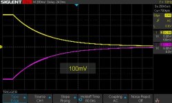
So in short, both rails have settled pretty much all the way by 200ms. If its of interest to other builders, I can post exactly what I used for all components. Huge thanks to all who gave me guidance here, @tombo56, @Trileru @Elvee - unless you think there is something else I should try, I am content to leave this as is for now. I attach a final scope shot here, vertical divisions 5V, 200ms on time base. I also include a shot of the shutdown, but bear in mind there is equal load (150mA) on both rails.
LM337 denoiser setup: I tried 100uF and 47uF coupling caps, both gave very similar startup times to 220uF - about 2.5s to hit target voltage. In the end, I replaced the 22uF cap for coupling and I get a time to voltage of ~170-200ms.
LM317 denoiser setup: I tried 22uF and 100uF coupling caps, and both still showed the slight overshoot, i.e. no difference to 220uF coupling, so I refitted the 220uF.
So in short, both rails have settled pretty much all the way by 200ms. If its of interest to other builders, I can post exactly what I used for all components. Huge thanks to all who gave me guidance here, @tombo56, @Trileru @Elvee - unless you think there is something else I should try, I am content to leave this as is for now. I attach a final scope shot here, vertical divisions 5V, 200ms on time base. I also include a shot of the shutdown, but bear in mind there is equal load (150mA) on both rails.
Attachments
To make sure they work properly, you can try to connect the outputs to the phono or mic input of an amplifier, via a 220nF capacitor.
Make the test with the circuit operating normally, then short the E and C of the corresponding transistor: you should hear an increase in the noise, as this disables the denoiser
Make the test with the circuit operating normally, then short the E and C of the corresponding transistor: you should hear an increase in the noise, as this disables the denoiser
- Home
- Amplifiers
- Power Supplies
- D-Noizator: a magic active noise canceller to retrofit & upgrade any 317-based VReg