I did do a measurement for 5-6Vout and worked fine, similar to the sim. I think I mentioned it last time I did measurements.
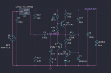
For 5Vout in the circuit version you mentioned you should lower R11 from 620K to around 470K-500K if using BC3x7 pair. Might be different for other BJTs.
For 5Vout in the circuit version you mentioned you should lower R11 from 620K to around 470K-500K if using BC3x7 pair. Might be different for other BJTs.
Hi I am interrest also for the 5V parts number you gave and also 20V. I think a no noiser or denoiser could be good at supply some usb to i2s devices as the JLsounds or Wave I/O as some IanCanada front ends.
I have collected the parts for the pcb and I will report with chrono in hand about the swing. Many thanks Trileru and the Elvee for the impressive work and sharing.
How ampers can it output please, the rating of the Lm317 ? 1,5 A ?
I have collected the parts for the pcb and I will report with chrono in hand about the swing. Many thanks Trileru and the Elvee for the impressive work and sharing.
How ampers can it output please, the rating of the Lm317 ? 1,5 A ?
Yes. If you want higher current you could use LM338.How ampers can it output please, the rating of the Lm317 ? 1,5 A ?
I'll check the values for 20Vout and post them later.


Many thanks...I will try with two monoboards a + gnd - power supply. But I come back first with the 6.3V or 5V to report the chrono of voltage swing.
Hi, my appologies as I wanted to report faster about the voltage swing of the mono board of Trileru page 115 for 6.3 V and also 20V but some parts are missing from my last command like the 1R smd and the 3k3 for the 20V
Do the two diodes needed around the LM317 ( protection diodes ?) As the ferittr smd bead for the bc 337 ?
Also I have a doubt on the 22uF...should not have a too much low esr with the LM317, no ? Better a bad esr cap there, basic cap ?
Do the two diodes needed around the LM317 ( protection diodes ?) As the ferittr smd bead for the bc 337 ?
Also I have a doubt on the 22uF...should not have a too much low esr with the LM317, no ? Better a bad esr cap there, basic cap ?
Attachments

Looking good!
You can use it without the protection diodes but I'd add them when possible.
There's no smd ferrite footprint on that PCB. You can use a THT one and put it on the BJT pin.
You could hack in a smd one if you're careful, but I have not tested it like that.
The 22uF can be any type of capacitor, any regular electrolytic should work fine.
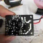
Thanks Trileru... I hope not to need this ferrite bead as the BC 337 is soldered.
Btw, is it possible to swap the 220/330 uF cap by a bipolar a la Muse ES or better to keep it polarized ? I ask because those Nichicons bipolar have very low noise floor but do not know if it matters here?
Btw, is it possible to swap the 220/330 uF cap by a bipolar a la Muse ES or better to keep it polarized ? I ask because those Nichicons bipolar have very low noise floor but do not know if it matters here?
Few mentions:Hi, my appologies as I wanted to report faster about the voltage swing of the mono board of Trileru page 115 for 6.3 V and also 20V but some parts are missing from my last command like the 1R smd and the 3k3 for the 20V
Do the two diodes needed around the LM317 ( protection diodes ?) As the ferittr smd bead for the bc 337 ?
Also I have a doubt on the 22uF...should not have a too much low esr with the LM317, no ? Better a bad esr cap there, basic cap ?
I think I see 0R resistors installed on the smd jumper footprints. You can just fill them with solder, they'll bridge at some point.
Also I might have forgotten that there is a series 0805 SMD footprint, with the output capacitor, to ground. I used an inductor in the Kicad project, but it can also be used for a resistor.
In this case you could also try to use a 0805 SMD ferrite bead.
It can also be used with a resistor to correct the output capacitor's ESR to get it to around 0.2R total, in case you're using a lower ESR capacitor in that spot. But ideally you'd use that Panasonic FC 100uF/63V (8mm diameter one) as I had good success with it.
Thanjs Trileru
Yep I see after than the fc100/63 was the heigthest casing with diffetent pitch leg...
I saw there was this jumper number 6 for the output cap. I soldered it but I wonder if this 100 uF will not be better near the final load as often there is some trace length in the devices in case of Lm317 replacement.
Ah I found 3R sms that could replacecthe 1R...with 47 nF it could do it...
But the 3k3 must wait a next Mouser purchase for the 20V swing timing test.
You can alter R12/R13 in the attached schematic if it helps you with the values. R12 should be between 120R-240R.
Use a calculator like this to figure out what values result in 20Vout.
The output capacitor is needed so the regulator doesn't oscillate. You'd most likely have a capacitor near the final load.
The 3R resistor is on the high side, install two in parallel if possible, 1.5R should work fine in that spot. 47nF is ok but don't go higher.
Attachments
Thanks Trileru for all the inputs.
I found a shop in the next big town (Called Paris) I visit not very often since covid as I have no car. I should source the pots and the rigth parts so I will report in June.
Snail guy...
I found a shop in the next big town (Called Paris) I visit not very often since covid as I have no car. I should source the pots and the rigth parts so I will report in June.
Snail guy...
Hi Trileru,
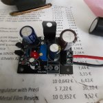
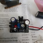
Finally I was given a 180R and 2k7 to try the 20V and measure the drift voltage chrono at switching on.
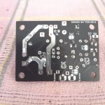
The pcb didn't work. I think there is an error in the gerbers: led is not tigthed to the R3 resistor Pot but to the V+ output. The little vias marked Voutput / gnd are shorted when tge pcb is unpopulated. When the pcb is populated with the rigth jumpers the main Vout and Gnd where there is the output plug is shorted.
Finally I was given a 180R and 2k7 to try the 20V and measure the drift voltage chrono at switching on.
The pcb didn't work. I think there is an error in the gerbers: led is not tigthed to the R3 resistor Pot but to the V+ output. The little vias marked Voutput / gnd are shorted when tge pcb is unpopulated. When the pcb is populated with the rigth jumpers the main Vout and Gnd where there is the output plug is shorted.
On the pcb, the led pin that is close to the 22 uF cap is buzzing with the dvm on both the gnd and the V output. So also on two pins of the R pot
The other led pin that goes to the BC ic does not go to R pot pins...
The other led pin that goes to the BC ic does not go to R pot pins...
Attachments
Use resistor measurement and check to be under 1ohm. The buzz function is working if the resistance is under some tens of ohms and is also buzzing on electrolitic capacitors.
I used the continuity checking...the led is not connected to the trimming pot but to R8 which is unpopulated as it is a resistor (non trimmable as fixed value choice) that goes to gnd. I think it just lacks the junction with trimmer when r8 is left unpopulated.
But the other pb is the Vout and Gnd on the output plug is shorted. Maybe here I made a jumper mistake.
Imo better to use the last design but not the one before which is the one JLpcb sent me. But I think I can easily jump it with a wire.
I report if I can hack the pcb, or maybe I made a mistake...
I jumped J3, J5, J6.
If you are using the CCS then R8 must be populated. If you are not using the CCS then the LED +R8 must not be populated.
Can you tell me what version are you trying to build? So give you the setup for each jumper.
Can you tell me what version are you trying to build? So give you the setup for each jumper.
- Home
- Amplifiers
- Power Supplies
- D-Noizator: a magic active noise canceller to retrofit & upgrade any 317-based VReg