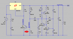
Thank you very much for sharing.I finished the PCB designs for NoNoiser: single LM317 / single LM337 / dual LM3x7.
The singles got a bit longer at 51mm x 35mm.
The dual got a bit shorter at 57mm x 53mm.
There's jumpers for all denoiser circuit configurations including switching back to the classical two-resistor LM3x7 implementation.
I attached the Kicad projects along with PDFs for schematics, diy pcb and gerbers.
BJT pinouts are for BC3x7 pair. If you use other BJT mind the pinouts.
Previous measurements were made with the LM317 PCB I attached in this post. I didn't test the dual version so you make that at your own risk.
I wonder if I can use the dual NoNoiser for powering a phono preamp +24V/-24V <1.0A
That is the phono section of my preamp that now is powered via split psu with 4X4700uF filter caps followed by LM7824/7924 fixed voltage regulators.
Last edited:

In the picture below see the changeThank you very much for sharing.
I wonder if I can use the dual NoNoiser for powering a phono preamp +24V/-24V <1.0A
Attachments
Do you mean I should alter the value of R5 to 175K to get the 24V output?In the picture below see the change
I am a bit confused, the schematic you posted is different than the one Trileru has uploaded with the files.
Last edited:
I think the schematic is the same.
You need to alter R5 to 175K for 24Vout. The NoNoiser uses a different scheme to set the output voltage.
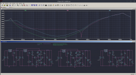
Also you might have to lower C3. LTSpice shows that for a similar response as a LM317 + denoiser (1.9k with 220uF) you can adjust C3 for 24Vout NoNoiser (R5=175k) to 3.3uF. Maybe stick a 10uF if you don't have a smaller electrolytic.
edit:
you can check Elvee's post for the math for setting Vout with the NoNoiser.
on the dual pcb I forgot to adjust R1's value to 2.7k for NoNoiser, in the project's schematic. if there's something you're not sure about (PCB part values for different configurations) it's best to ask here.
You need to alter R5 to 175K for 24Vout. The NoNoiser uses a different scheme to set the output voltage.
Also you might have to lower C3. LTSpice shows that for a similar response as a LM317 + denoiser (1.9k with 220uF) you can adjust C3 for 24Vout NoNoiser (R5=175k) to 3.3uF. Maybe stick a 10uF if you don't have a smaller electrolytic.
edit:
you can check Elvee's post for the math for setting Vout with the NoNoiser.
on the dual pcb I forgot to adjust R1's value to 2.7k for NoNoiser, in the project's schematic. if there's something you're not sure about (PCB part values for different configurations) it's best to ask here.
Last edited:
You can de-noise a Maida Regulator, but need a high voltage PNP for the CCS -- something like a KSP92.You should be able to. I think one quirk of the CCS is you don't need to adjust any denonising circuit values for various Vout.
I think I've done some simulations for Maida with the simple denoiser, some time back. In the case of the simple denoiser you just need a large enough resistor.
I want to try something to see if it helps low voltage output, say 5V. The CCS becomes harder to use for lower Vout.
I'm not sure how critical it is for the CCS itself to be powered from Vout. If you have another higher voltage available in the case (say 12V-15V for opamps) then you could use that to power the denoising circuit. The CCS has some (small) PSRR as well.
I wonder if this trick could be used for Maida to get around HV parts or HV waste as heat.
You will need to test to see if that works, but I'm suspecting the higher voltage source would contaminate the low noise output through the grounds needing to be tied together. Of course, I may be totally off base.
Here's a sim for what I was proposing. I though about powering the CCS from the input of the regulator but there seems to be some strange interaction that I don't understand.
But if I power it from a separate LM317 (stock application without Cadj), there seems to be an improvement on 5Vout vs just resistor. I don't think the CCS can even be used for 5Vout.
But if I power it from a separate LM317 (stock application without Cadj), there seems to be an improvement on 5Vout vs just resistor. I don't think the CCS can even be used for 5Vout.
Attachments
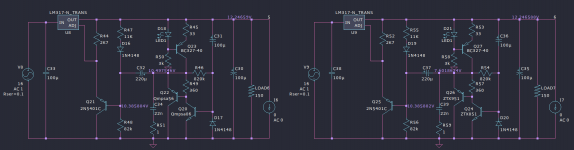
Another thing you should consider is the fact that for different denoiser transistors (Q20/Q24 in the attached photo) there seems to be a different DC offset on the denoiser side of the coupling capacitor (C32/C37).
For lower Vout you might need to rotate that capacitor. And I guess that might eat into the CCS performance as well?
edit: I exagerated the current with 33R.
For lower Vout you might need to rotate that capacitor. And I guess that might eat into the CCS performance as well?
edit: I exagerated the current with 33R.
Attachments
Following the schematic you last uploaded at post #2,340 and adjusting the values of R1 to 2.7K, R5 to 175K and C3 to 3.3uF (as advised in order to get 24Vout) do I have to lower the value of C4 too or keep it at 100uF?I think the schematic is the same.
You need to alter R5 to 175K for 24Vout. The NoNoiser uses a different scheme to set the output voltage.
Also you might have to lower C3. LTSpice shows that for a similar response as a LM317 + denoiser (1.9k with 220uF) you can adjust C3 for 24Vout NoNoiser (R5=175k) to 3.3uF. Maybe stick a 10uF if you don't have a smaller electrolytic.
edit:
you can check Elvee's post for the math for setting Vout with the NoNoiser.
on the dual pcb I forgot to adjust R1's value to 2.7k for NoNoiser, in the project's schematic. if there's something you're not sure about (PCB part values for different configurations) it's best to ask here.
Last edited:
I have made some systematic tests on a number of 337's, since it is more temperamental than the 317 and can be difficult to tame.
The optimal compensation values vary somewhat with the source of the 337, but a safe, one-size-fits-all combination is 47nF-4.7ohm.
Recently fabricated samples do not require values that aggressive, but if you want to ensure a good stability without making detailed tests of the transient behaviour, they are a safe option and the impact on the HF performance of the denoiser is minimal.
These are valid for an ordinary transistor: the recommended type is BC327, but any other general-purpose type will also work: BC558, 2N3904, 2N2907, etc. (non-exhaustive).
A high perf transistor like the ZTX950 can also be used, but in the denoiser the performance gain over a BC327 will be small. For the dienoiser and nonoiser, it will significantly lower the noise floor.
The gain selection of the transistor is mostly indifferent: -16, -25, -40 or unselected types will work equally well.
The denoiser's performance is dictated by the transconductance, which does not depend on the gain, except that a higher gain type will bias itself at a slightly larger current, but this effect is compensated by the higher Hoe of higher beta transistors: the Early voltage is inversely correlated to the betaa, for a given process.
Stay away from "exotic" types, like VHF/UHF transistors: apart from problems, they will bring nothing to the denoiser
hi Elvee
Thanks for such a great solution!
You mentioned here the most secure way of stabilizing compensation for the 337.
Should I modify the denoiser as follows?
Thanks again
That's my recommendation, based on a (non-exhaustive) number of samples. Your mileage may vary, but the values should normally be safe enough, unless your 317 is really an odd, exotic beast.
Also read Trileru's posts about the subject, they are highly informative
I said to myself that i'll measure original d-noizator but i have been busy for quite some time. Finally i found spare time and tested it with my simple LNA and HP 334A as measuring equipment. Conditions for testing we're a bit unusual.Input voltage around 11V,output voltage 6.3V(maybe a bit too low for d-noisator work properly), current 0.6A. Unusual test conditions are cause i'm gonna use it as for ecc88 heater so i wanted to test it in real working conditions. I know it's overkill but it's cheap,simple and you can get parts everywhere so why not used it and it was perfect time to measure it.
Results we're a bit disappointing. Input ripple voltage was 0,25Vrms and output 7uVrms so after i do math i get around 91dB ripple rejection, which is more or less 10dB better then normal lm317(80db typical ripple reduction). Not sure if result is bad cause of low output voltage or something else. I'll test it under same current consumption but around 15V output voltage and see what result i get.
Results we're a bit disappointing. Input ripple voltage was 0,25Vrms and output 7uVrms so after i do math i get around 91dB ripple rejection, which is more or less 10dB better then normal lm317(80db typical ripple reduction). Not sure if result is bad cause of low output voltage or something else. I'll test it under same current consumption but around 15V output voltage and see what result i get.
The typical 30dB improvement applies to a 12V configuration. At 6V, with the values unchanged, there will be a degradation of a few dB, but not 20dB or even 10dB.
I suspect that some additional ripple leaks through a non-ideal GND configuration, a magnetic coupling of the ripple current to the regulator or the denoiser, or something similar.
To keep the same 30dB performance at 6V, you can scale all the resistors of the denoiser: halve them in your case.
I suspect that some additional ripple leaks through a non-ideal GND configuration, a magnetic coupling of the ripple current to the regulator or the denoiser, or something similar.
To keep the same 30dB performance at 6V, you can scale all the resistors of the denoiser: halve them in your case.
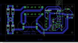
This is PCB, i placed one extra transistor in parallel to LM317 if extra current is needed but in tested configuration i used plain Lm317 dnoizator so R10,11 and T1 are not used. Maybe mistake could be that i placed dnoizator parts in between of power paths and 0,6A is not small current so there could be interference from magnetic coupling.
I tried to keep power gnd away from local lm317 and dnoizator gnd so those two meet only at output capacitor.
Thanks for info and i'll try test this PCB with smaller output current at different output voltages and see what results i get.
I tried to keep power gnd away from local lm317 and dnoizator gnd so those two meet only at output capacitor.
Thanks for info and i'll try test this PCB with smaller output current at different output voltages and see what results i get.
Attachments
- Home
- Amplifiers
- Power Supplies
- D-Noizator: a magic active noise canceller to retrofit & upgrade any 317-based VReg