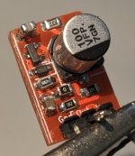
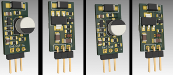
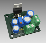
I finally got to test the three legged regulator pcbs from post #1940. A bit harder to correctly test them as they are small and load+ DC in + sense cable make for a non-optimal measurement setup.
Even so the dienoiser PSRR came out at around 110dB. Denoiser PSRR came out at around 105dB. Not the best but maybe it could be better with better measurement setup. Noise seems typical for de/dienoiser.
For LM317 version I used 2x10uF output caps, 150mOhm resistor and the diy inductor.
For LM337 it's more finicky. Dienoiser worked with 3x10uF output caps and 2x50mOhm in parallel (also with the diy inductor). The denoiser worked with 50mOhm instead of 25mOhm.
Compensation network was 47nF+1R for both.
Measurement pictures:
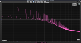
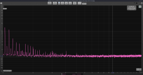
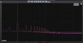
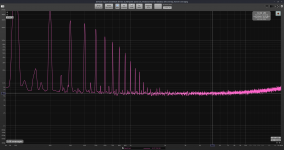
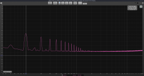
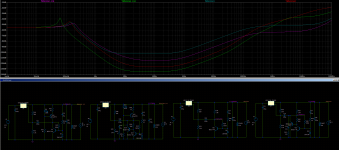
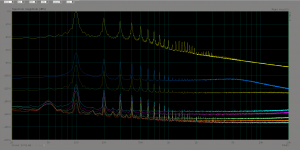
1. input ripple
2. LM317 denoiser PSRR
3. LM317 denoiser noise
4. LM317 dienoiser PSRR
5. LM317 dienoiser noise.
I made a revision of the pcbs to also include the protection diodes.
Even so the dienoiser PSRR came out at around 110dB. Denoiser PSRR came out at around 105dB. Not the best but maybe it could be better with better measurement setup. Noise seems typical for de/dienoiser.
For LM317 version I used 2x10uF output caps, 150mOhm resistor and the diy inductor.
For LM337 it's more finicky. Dienoiser worked with 3x10uF output caps and 2x50mOhm in parallel (also with the diy inductor). The denoiser worked with 50mOhm instead of 25mOhm.
Compensation network was 47nF+1R for both.
Measurement pictures:
1. input ripple
2. LM317 denoiser PSRR
3. LM317 denoiser noise
4. LM317 dienoiser PSRR
5. LM317 dienoiser noise.
I made a revision of the pcbs to also include the protection diodes.
Attachments
-
 input_ripple.png248.8 KB · Views: 653
 -
 Screenshot from 2021-04-10 14-22-28.jpg68.6 KB · Views: 254
 -
 Screenshot from 2021-04-10 14-22-10.png776.4 KB · Views: 286
 -
LM337N_SOT223.zip133.2 KB · Views: 122
-
LM317N_SOT223.zip130.9 KB · Views: 127
-
 Screenshot from 2021-04-10 14-04-32.png797.5 KB · Views: 277
 -
 N_LM317N_dienoiser.png180.6 KB · Views: 617
 -
 LM317N_dienoiser.png178 KB · Views: 611
 -
 N_LM317N_denoiser.png192.4 KB · Views: 606
 -
 LM317N_denoiser.png193.6 KB · Views: 616
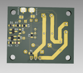
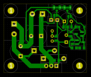
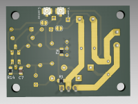
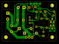
Made the LM338 pcb which should be good for the full 5A output. As long as you fill the power traces with solder.
For 5A it's best you have a separate rectification board, so this pcb is only DC input.
If you want a THT denoiser board ask and I might do it when I find the time. I made the denoiser circuit SMD for the smallest board size. It's around 35mm x 42mm.
I have not tested this design so you make it at your own risk.
The board is diyable with a topside link.
edit: I added a pot footprint, forgot about it.
Attachments
Last edited:
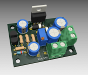
This is the THT denoiser version for LM338. Size is around 47mm x 35mm. Compensation network is still smd.
Instead of the U.FL connectors you can directly solder the wire on the pcb. Twist them both together until the sense point.
Instead of the U.FL connectors you can directly solder the wire on the pcb. Twist them both together until the sense point.
Attachments
I was playing with LTSpice and noticed that replacing the top denoiser resistor with a LED CCS improves the performance of the circuit. For LM317 seems it does less than it does for the discrete regulator versions, at the same 5-7mA current.
But if you can spare around 30mA on the output, then it seems you can get an extra 12dB or so of PSRR for the denoiser. The dienoiser also gets some extra performance (about 6dB) but not as much as the denoiser.
Output impedance also seems to improve.
I have not measured this yet, it's all in LTSpice atm.
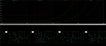
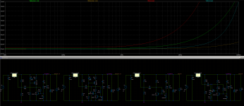
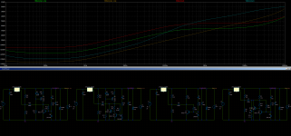
Added comparisons between denoiser and dienoiser with their corresponding ccs version. 2nd and 3rd photo are for output impedance comparison.
But if you can spare around 30mA on the output, then it seems you can get an extra 12dB or so of PSRR for the denoiser. The dienoiser also gets some extra performance (about 6dB) but not as much as the denoiser.
Output impedance also seems to improve.
I have not measured this yet, it's all in LTSpice atm.
Added comparisons between denoiser and dienoiser with their corresponding ccs version. 2nd and 3rd photo are for output impedance comparison.
Attachments
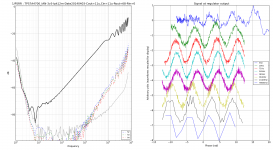
I got to make some measurements with CCS instead of the resistor and I got good results.
I measured the CCS version at 7mA and 22mA through the denoiser circuit. I measured this for both denoiser and dienoiser.
I used a LM317N from TI (performs better than a regular LM317), 220uF filter capacitance so input ripple is at around 0dBV, 150R load at 11.3Vout. The schematics in the first picture shows the exact values and parts I used in measurement.
I also did a sanity check and measured Cadj (220uF) and the simple configuration for the LM317N.
PSRR values:
1. simple LM317N - 64.7dB
2. Cadj 220uF - 83.5dB
3. normal denoiser - 113.8dB
4. 7mA CCS denoiser - 117.6dB
5. 22mA CCS denoiser - 123.8dB
6. normal dienoiser - 137.5dB
7. 7mA CCS dienoiser - 142.8dB
8. 22mA CCS dienoiser - 148.2dB
For 7mA I used 150R for current setting and for 22mA I used 47R.
Apart from the increase in PSRR it seems that noise goes lower as well by using the CCS.
For denoiser it dropped from around 7nV/sqrtHz to about 4.2nV/sqrtHz at 7mA and to 1.8nV/sqrtHz at 22mA.
For dienoiser it dropped from around 0.91nV/sqrtHz to 0.78nV/sqrtHz at 7mA and to 0.75nV/sqrtHz at 22mA. I subtracted my LNA noise from the values.
For denoiser BJTs I used the BC8x7 pair. For the CCS BJT I used a 2SA970, but you could use a BC560. The LED is red and draws around 3mA.
You can decide if it's worth the extra 15mA total for the higher performance.
The discrete Mosfet supply benefits of more performance at 7mA but not much extra at 22mA.
So seems that LM317N can do 148dB of PSRR with around 750pV/sqrtHz noise (10kHz-20kHz) with this improvement.
Maybe someone else can confirm this?
Attachments
I like this circuit. OK, some criticism 😀
Your THT board has good ground layout.
However the 3 terminal tiny board has a problem that's common and unavoidable with this kind of design: its GND is connected to the carrier PCB with only 1 GND pin.
So if there is HF noise on the input, it goes through the input cap of your regulator board, but the impedance of the ground pin is too high, so it can't shunt the noise to ground. Instead, it lifts the whole GND on the regulator board, and goes straight into the output via the output decoupling cap.
To get good performance with 3-terminal mini board the input cap must not be on the miniboard. It has to be on the carrier board, with good layout, like you did in your THT board.
Attached is PSRR of 3-terminal miniboard with TPS7A4700, -20dB PSRR at 10kHz, not really spectacular.
How did you measure PSRR?
Attachments
Yes I know it's not ideal, you trade PSRR for small size. The loss of PSRR performance is seen in the measurements. It's a bit finicky anyway with the diy aircore inductor. Not sure if people will use it.
I used a 60dB LNA for measurements.
I used a 60dB LNA for measurements.
I mean, did you measure it mounted on a board with the 3 pin connector as it would be used, or did you connect the analyzer probes directly to the miniboard? If you do the latter, the effect I described won't show up, because it is caused by the impedance of the ground pin, and if the analyzer probes are connected directly to the miniboard, the ground pin is not part of the circuit.
I had the pcb into a metal case with LNA coax cable soldered on the output of the board, and main filter capacitor was outside the case, about 30cm away, next to the bridge. But I've not tested it in any application.
AH okay! Misunderstanding. I thought you injected a signal in the input and measured the output to get PSRR, but you're doing a ratio of the mains harmonic before and after the regulator, right? In this case there is not much above a few kHz, so it doesn't tell a lot about PSRR above this...
I got to make some measurements with CCS instead of the resistor and I got good results.
I measured the CCS version at 7mA and 22mA through the denoiser circuit. I measured this for both denoiser and dienoiser.
I used a LM317N from TI (performs better than a regular LM317), 220uF filter capacitance so input ripple is at around 0dBV, 150R load at 11.3Vout. The schematics in the first picture shows the exact values and parts I used in measurement.
I also did a sanity check and measured Cadj (220uF) and the simple configuration for the LM317N.
PSRR values:
1. simple LM317N - 64.7dB
2. Cadj 220uF - 83.5dB
3. normal denoiser - 113.8dB
4. 7mA CCS denoiser - 117.6dB
5. 22mA CCS denoiser - 123.8dB
6. normal dienoiser - 137.5dB
7. 7mA CCS dienoiser - 142.8dB
8. 22mA CCS dienoiser - 148.2dB
For 7mA I used 150R for current setting and for 22mA I used 47R.
Apart from the increase in PSRR it seems that noise goes lower as well by using the CCS.
For denoiser it dropped from around 7nV/sqrtHz to about 4.2nV/sqrtHz at 7mA and to 1.8nV/sqrtHz at 22mA.
For dienoiser it dropped from around 0.91nV/sqrtHz to 0.78nV/sqrtHz at 7mA and to 0.75nV/sqrtHz at 22mA. I subtracted my LNA noise from the values.
For denoiser BJTs I used the BC8x7 pair. For the CCS BJT I used a 2SA970, but you could use a BC560. The LED is red and draws around 3mA.
You can decide if it's worth the extra 15mA total for the higher performance.
The discrete Mosfet supply benefits of more performance at 7mA but not much extra at 22mA.
So seems that LM317N can do 148dB of PSRR with around 750pV/sqrtHz noise (10kHz-20kHz) with this improvement.
Maybe someone else can confirm this?
Great results for a simple addition.
Can you please indicate if similar results can be obtained for the negative regulator?
CCS - further question
I have pcbs for the original no-noiser circuit. Realise that the dienoiser circuit is slightly different.
Can the CCS be implemented in the no-noiser circuit with some benefit?
Regret I have not learnt simulation in LTSpice and may not have the skills to detect instability to take an experimental approach
AH okay! Misunderstanding. I thought you injected a signal in the input and measured the output to get PSRR, but you're doing a ratio of the mains harmonic before and after the regulator, right? In this case there is not much above a few kHz, so it doesn't tell a lot about PSRR above this...
I just used another LM317 board, and instead of using a denoiser circuit I directly injected audio signal into the ADJ pin.
Tested the CCS denoiser with this and seems that between 1kHz and 20kHz there's around 10dB loss in PSRR. I didn't calibrate anything, just wanted to see how much it dips and it's not much. So PSRR should be solid in the audio range.
Great results for a simple addition.
Can you please indicate if similar results can be obtained for the negative regulator?
Yes the LM337 should behave the same largely.
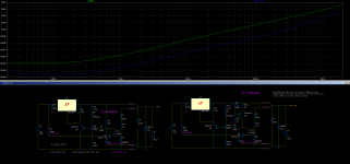
I have pcbs for the original no-noiser circuit. Realise that the dienoiser circuit is slightly different.
Can the CCS be implemented in the no-noiser circuit with some benefit?
Regret I have not learnt simulation in LTSpice and may not have the skills to detect instability to take an experimental approach
I tested in LTSpice and seems it should work. I attached a sim result.
edit: looking at different simulation results the CCS doesn't seem to affect the phase much, so it shouldn't change the stability requirements. I used the same compensation values I used with the normal dienoiser and didn't have issues.
Attachments
Last edited:
Thanks a lot! Really encouraging. Will try it at some stage in an actual circuit. Currently one pair of the boards are installed in my Nakamichi 582 tape deck that had to be opened for a belt upgrade. It gave a very good improvement over the earlier std 78xx/79xx board.
Hi all,
I'm a latecomer to this thread - and am trying to catch up, but there are 220 pages! Is there is a list of suitable transistors anywhere? Or are we limited to the BD330/2n4401 from the first/last posts?
I have a range of other transistors here - BD140, MJE253, 2n3906, 2n5087 - are any of them suitable?
Last edited:
I just realised I typed BD330 instead of BC330 - so the reverse polarity 🙄
Having read a little more, I take it any NPN will "work" but some will be better than others.....
Having read a little more, I take it any NPN will "work" but some will be better than others.....
Is there a current limit with the De Noiser design ? Would like to be able to add on to a LT-1083 based power supply feeding a mixing console pulling about 4 A.
- Home
- Amplifiers
- Power Supplies
- D-Noizator: a magic active noise canceller to retrofit & upgrade any 317-based VReg