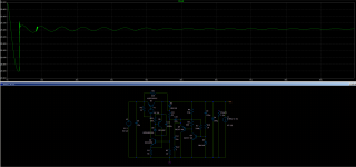
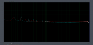
While AC load of 4A peak there's a sag of around 700mV, but with a 4A constant load the output voltage drops 1.2V. For 7.5kohm load the output is 30V.
For AC load I don't think those thicker areas are oscillation. They have the same frequency as the load. Might be some output impedance variation? The settle seems typical to denoiser.
Maybe Q2 needs more base current for less droop?
For AC load I don't think those thicker areas are oscillation. They have the same frequency as the load. Might be some output impedance variation? The settle seems typical to denoiser.
Maybe Q2 needs more base current for less droop?
Attachments

Had some time for testing remote sensing with normal wire and coaxial wire. There's better results with coaxial but I need to find a different GND point for the coax shield, it's not good that it's near the GND sense.
I used around 20cm of wire for power delivery to the 150R load. All sense wires were around 15cm (didn't have longer thin coax).
Had to turn on different gear around the desk so to have some noise around the measurement setup. With cleaner EM environment the differences were not so clear.
Attached pictures are as follows:
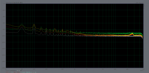
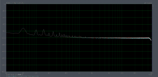
1. comparison between normal sense wires, coax wires and local sensing (output of pcb). Green trace is local sensing, yellow trace for normal sensing wires, red trace for coax sensing wires. The grey trace is local sensing with load directly on the output connector of the pcb (with clean environment) so to have a best case scenario for performance comparison.
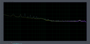
2. Measurements with normal wires, one of them (the worse one) is with the wires not closely together. Having them apart picks up extra noise.
3. Same thing but for coax. They also need to be kept close together.
4. I used sensing on the output of the pcb with load on the output connector, but used 15cm of normal wire and coax between the denoiser coupling cap (ADJ connection) and pcb. There doesn't seem to be a difference. I also put the soldering tip close to the wire and there wasn't any difference. Doing that near the sense wires would show up on the measurement graph. So this node isn't particularly sensible.
I didn't have a denoiser add-on to test it at the load. The last photo is a sort of simulation of that. It doesn't have power delivery wires as the denoiser and load are on the pcb.
This test was to understand what approach is better for supplies with the denoiser onboard. Ideally you'd have the denoiser built into the pcb near the load and run the signal wire back to the regulator.
So using coax gives slightly better results. Using sense wires helps with lowering the noise floor at higher frequencies. In all remote sensing approaches there's a loss of PSRR, more than 10dB.
Local sensing seems like a good compromise. Using sense wires might give worse results depending on the environment and also depending on how you route them and if you don't keep them close together.
edit: I used the latest discrete pcb but I think this is typical to the denoiser circuit not the regulator.
I used around 20cm of wire for power delivery to the 150R load. All sense wires were around 15cm (didn't have longer thin coax).
Had to turn on different gear around the desk so to have some noise around the measurement setup. With cleaner EM environment the differences were not so clear.
Attached pictures are as follows:
1. comparison between normal sense wires, coax wires and local sensing (output of pcb). Green trace is local sensing, yellow trace for normal sensing wires, red trace for coax sensing wires. The grey trace is local sensing with load directly on the output connector of the pcb (with clean environment) so to have a best case scenario for performance comparison.
2. Measurements with normal wires, one of them (the worse one) is with the wires not closely together. Having them apart picks up extra noise.
3. Same thing but for coax. They also need to be kept close together.
4. I used sensing on the output of the pcb with load on the output connector, but used 15cm of normal wire and coax between the denoiser coupling cap (ADJ connection) and pcb. There doesn't seem to be a difference. I also put the soldering tip close to the wire and there wasn't any difference. Doing that near the sense wires would show up on the measurement graph. So this node isn't particularly sensible.
I didn't have a denoiser add-on to test it at the load. The last photo is a sort of simulation of that. It doesn't have power delivery wires as the denoiser and load are on the pcb.
This test was to understand what approach is better for supplies with the denoiser onboard. Ideally you'd have the denoiser built into the pcb near the load and run the signal wire back to the regulator.
So using coax gives slightly better results. Using sense wires helps with lowering the noise floor at higher frequencies. In all remote sensing approaches there's a loss of PSRR, more than 10dB.
Local sensing seems like a good compromise. Using sense wires might give worse results depending on the environment and also depending on how you route them and if you don't keep them close together.
edit: I used the latest discrete pcb but I think this is typical to the denoiser circuit not the regulator.
Attachments
Last edited:
No but I don't think it can bring much difference. I think the issue is that the power delivery wires pick up noise anyway. I think the only thing you can do is have a clean environment where you install the supply. I don't think you can expect the best performance that the denoiser is capable of without also taking other measures. I think this might be true for other low noise supplies.
If I find the time I might test this as well.
If I find the time I might test this as well.
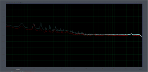
I attached measurements for the same regulator pcb, no cap multiplier in circuit for both measurements, 150R load directly on the output connector, sensing on the pcb output, so best case scenario for the regulator, one measurement is with clean environment, the other is with most stuff turned on on the desk, soldering station etc.
As you see, even with the shortest connections between everything the whole circuit still picks up some crap.
Clean measurements for supplies do not transfer over when applied to gear. Other considerations have to be taken when applying the supplies to gear. At this level of noise there's a lot of things that matter.
edit: the red trace is from the test with longer ADJ wire but I don't think it matters.
Attachments
Last edited:
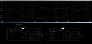
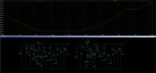
I have updated the tht designs for LM317 single and dual versions. I rectified the grounding for the u.fl connectors based on the findings from the latest measurements. I kept the version to 1.4. I also made version 1.5 for each with a different capacitance multiplier setup. Same number of parts, just that instead of a Darlington pair the capacitance multiplier uses a Sziklai Pair with PNP for positive pass transistor. You can get a lower drop across it this way, around 1V instead of the about 1.5V of the Darlington version. Might be useful for some.
The PSRR performance is similar to 1kHz which covers the ripple. You can use BD140 for example if the current is not high. For lower transistors 2N5551/2N5401 seem to give better results than BC337 or BC550.
I attached a sim with the difference between the two versions. Graph is with output of cap multipliers and regulators output.
Boards are all diy-able but singles have a top side link. You don't need to install it if you make the boards at fab house as there's a top trace between the holes.
There's also the smd RLC network alternative for the tht output caps for all versions.
For 200-300mA you don't have to put a heatsink on the cap multi pass transistors. If you don't want to use the capacitance multiplier you can short pins 2-3 from pass transistors. For the Sziklai Pair the resistor from lower transistor to gnd has to be adjusted based on your input voltage as opposed to the Darlington pair. There isn't a recommended value for it.
Attachments
What if I use big electrolytic caps (eg 4700uF) after regulator with 15cm cable on load (preamp or dac) side? Which measurements will be altered with this situation?
Can the Mark Johnson VRDN do 5v or atleast 6 or 7 or is the 11v the absolute minimum.?
Thanks
Thanks
Hi Trileru,
What is your output capacitor and compensation network for d-noiser when use with lt3082? I use 22uf 10mohm capacitor and no compensation network, after 1 minute the output voltage still jumping between 7.5 to 7.8V
What is your output capacitor and compensation network for d-noiser when use with lt3082? I use 22uf 10mohm capacitor and no compensation network, after 1 minute the output voltage still jumping between 7.5 to 7.8V
Depends on your noise environment and how and where you sense the noise. You should have some local decoupling at the load.What if I use big electrolytic caps (eg 4700uF) after regulator with 15cm cable on load (preamp or dac) side? Which measurements will be altered with this situation?
Hi Trileru,
What is your output capacitor and compensation network for d-noiser when use with lt3082? I use 22uf 10mohm capacitor and no compensation network, after 1 minute the output voltage still jumping between 7.5 to 7.8V
I successfully used 22uF + 30-35mOhm + 30nH inductor. That 30nH are important. They can be provided by a tht cap usually. But I explained how you can make a small diy one in this post here:
D-Noizator: a magic active noise canceller to retrofit & upgrade any 317-based V.Reg.
10mOhm might be too low. Ceramic caps have ESR as well. Paralleling them lowers it, so with two 10uF in parallel I had to use 30mOhm I think, and with only one 22uF cap 20mOhm might be ok. But with ceramic caps you need that small extra inductance.
Last edited:
Depends on your noise environment and how and where you sense the noise. You should have some local decoupling at the load.
I successfully used 22uF + 30-35mOhm + 30nH inductor. That 30nH are important. They can be provided by a tht cap usually. But I explained how you can make a small diy one in this post here:
D-Noizator: a magic active noise canceller to retrofit & upgrade any 317-based V.Reg.
10mOhm might be too low. Ceramic caps have ESR as well. Paralleling them lowers it, so with two 10uF in parallel I had to use 30mOhm I think, and with only one 22uF cap 20mOhm might be ok. But with ceramic caps you need that small extra inductance.
This mean output connect to 30mOhm resistor to 30nH inductor to capacitor to ground right?
Yes you have to chain them. I don't think the order matters. You can use online calculators for the diy aircore inductor so you can adjust it to what thickness wire you have.
For best chances make the inductor for around 30nH, it's not critical if you get it 4-5nH up or down, but try to shoot for 30nH, then play with the resistor between 20mOhm and 30mOhm. It should work.
I tested some output caps for LM337 + dienoiser. I used the V1.4 board on which I inverted all polarities and swapped the dienoiser transistors. I bent the legs of the LM337 and installed it on the backside of the board.
Compensation network was 1x22nF +2x10nF sandwiched (42nF total) + 5R. I tried 3 capacitors and it worked with all three of them. I poked at the comp cap on both sides with metal tweezers and it recovered very fast. There doesn't seem to be any difference between measurements with either of the caps. I attached an overlay of all three measurements, can't remember which is which but the result seems identical with either.
Cap model numbers are: EEU-FR1E471LB, EEU-FR1E221 and MAL213666102E3. The 220uF/25V Panasonic FR I didn't expect to work as it's rather small size but seems to work fine. All three caps are 50mOhm or under for ESR.
I used a Fairchild LM337 regulator.
I plan on testing some more when I get the time.
Also since the difference was so small I made the two V1.4 and V1.5 versions for LM337 as well. Maybe someone finds it useful, or wants the set. You could also use it for positive rail with reversed connections if you want to use your favorite low ESR cap on the output. The only thing missing is the ESR correcting resistor from the output cap, since it's not needed for LM337 + de/dienoiser.
I didn't install the capacitance multiplier for this test. But I did put the 100uF following it, so the conditions match previous measurements.
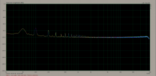
edit: I attached a comparison between the LM337 vs LM317 on the V1.4 board, with dienoiser for each. Red trace is LM317 and cyan is LM337 (one of the three caps). That extra 150/300Hz for LM317 might be due to the position of the board on my desk, I had it flipped for LM337 measurements. They seem to both perform almost identically. LM317 I think was ST flavor.
The measurement for LM337 should represent the performance of the dual board for LM337.
2nd edit: forgot to mention, also since it was rather simple I also added the LM337N SOT223 footprint on the back. It's rotated vs the positive version, worked out fine. Pin 2 is not connected to pin 4 but the device is connected internally between these pins. There isn't a negative version of LT3082 in SOT223 but maybe someone finds the footprint useful for testing SOT223 LM337N.
Compensation network was 1x22nF +2x10nF sandwiched (42nF total) + 5R. I tried 3 capacitors and it worked with all three of them. I poked at the comp cap on both sides with metal tweezers and it recovered very fast. There doesn't seem to be any difference between measurements with either of the caps. I attached an overlay of all three measurements, can't remember which is which but the result seems identical with either.
Cap model numbers are: EEU-FR1E471LB, EEU-FR1E221 and MAL213666102E3. The 220uF/25V Panasonic FR I didn't expect to work as it's rather small size but seems to work fine. All three caps are 50mOhm or under for ESR.
I used a Fairchild LM337 regulator.
I plan on testing some more when I get the time.
Also since the difference was so small I made the two V1.4 and V1.5 versions for LM337 as well. Maybe someone finds it useful, or wants the set. You could also use it for positive rail with reversed connections if you want to use your favorite low ESR cap on the output. The only thing missing is the ESR correcting resistor from the output cap, since it's not needed for LM337 + de/dienoiser.
I didn't install the capacitance multiplier for this test. But I did put the 100uF following it, so the conditions match previous measurements.
edit: I attached a comparison between the LM337 vs LM317 on the V1.4 board, with dienoiser for each. Red trace is LM317 and cyan is LM337 (one of the three caps). That extra 150/300Hz for LM317 might be due to the position of the board on my desk, I had it flipped for LM337 measurements. They seem to both perform almost identically. LM317 I think was ST flavor.
The measurement for LM337 should represent the performance of the dual board for LM337.
2nd edit: forgot to mention, also since it was rather simple I also added the LM337N SOT223 footprint on the back. It's rotated vs the positive version, worked out fine. Pin 2 is not connected to pin 4 but the device is connected internally between these pins. There isn't a negative version of LT3082 in SOT223 but maybe someone finds the footprint useful for testing SOT223 LM337N.
Attachments
Last edited:
On the positive feedback version it seems that bypassing the LED increases the PSRR performance by quite a bit. The regulator is now close to -157dB at 100Hz. It's more performant than the other version, in this configuration.
Also seems that there really isn't any difference between using LEDs, Zener or LM329 as far as PSRR, self-noise reduction and output impedance goes. There's some gains in tempco, but even with LEDs it's not so bad.
With 100k potentiometer it allows for lower value denoiser coupling cap. The simulation was made for 30V/100mA.
I could also get 30V/1A and 68V/1A output easy. At 68V the positive feedback version needs a way to keep the extra heat away from the transistors. Using low Vref and adding a resistor to ground from the lower transistor allows for heat sharing, thus allowing the same to-92 transistors to be used.
I could get 4A at 30V out of both circuits but at that point the lower transistors need to be replaced with more beefier ones. Performance doesn't degrade much at higher currents.
Seeing this performance I decided to start a new thread for these circuits. I made some pcb designs and for the positive feedback version I don't think there's a need for a capacitance multiplier anymore. Thus making the board smaller.
Should I make two different threads for each design or a single one for both?
edit: the bypass cap is quite large at around 2200uF, but it only sees the Vdrop of the LED so the physical size is small on the pcb. I think both circuits have the same number of parts.
For higher voltages PSRR gets very close to -160dB.
Attachments
Last edited:
DeNoiser Add-On Measurements
I did use some of Trileru's early SMD add-on boards to add a denoiser to my Hafler DH-110 preamplifier. I made the mistake of not taking measurements first because I was having having issues with my measurement system. I won't make that mistake again. Anyway, here are the results of the SMD denoiser add-on boards, everything below -100dB. The readings were taken midpoint on the boards positive and negative rails, not right at the regulator outputs, so the results are more realistic.
Positive Rail

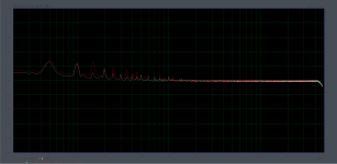
Negative Rail

I did use some of Trileru's early SMD add-on boards to add a denoiser to my Hafler DH-110 preamplifier. I made the mistake of not taking measurements first because I was having having issues with my measurement system. I won't make that mistake again. Anyway, here are the results of the SMD denoiser add-on boards, everything below -100dB. The readings were taken midpoint on the boards positive and negative rails, not right at the regulator outputs, so the results are more realistic.
Positive Rail
Negative Rail
Sent an email, there's something wrong on the positive rail, it should have the noisefloor at around -140dB as the negative rail.
@RickRay
Can you give a brief info on your measurement setup please? Which sound card do you use in order to see -140dB noise floor?
Can you give a brief info on your measurement setup please? Which sound card do you use in order to see -140dB noise floor?
I'm using a Focusrite Solo 3rd gen. with a +60dB Low noise Amplifier (LNA). The software is ARTA.
- Home
- Amplifiers
- Power Supplies
- D-Noizator: a magic active noise canceller to retrofit & upgrade any 317-based VReg