Yes I attached it.
Run that analysis out another decade further and look at impedance and group delay.
There's 30nH added to the output cap ESL. If you reduce it to 20nH or even 10nH it looks better. You are talking about the 40MHz+ area?
How much ESL does a normal electrolytic cap have? Are the longer ones more inductive?
How much ESL does a normal electrolytic cap have? Are the longer ones more inductive?
Yes I attached it.
What is the role of GLED blocks in this circuit?
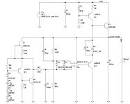
The initial part is reminiscent of an ALWSR regulator (WJ superreg.) only there is no op.amp here.
The LM329 is otherwise better than any zener diode, and a properly made GLED is better than the LM329.
Better tempco and higher current output without affecting the reference. This way there's a constant current through the reference.
The positive feedback version has a higher Vdrop across it, around 2.4-2.5V. If that isn't an issue then it seems to work fine.
The latest discrete version has a Vdrop of 0.5V across it and better performance.
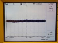
I tested the latest one with a tda7297 amp and looked at the output with the 60dB LNA. I used the cap multiplier that I used on the previous LM317 boards. The cap multiplier uses a MJE15032 which is NPN and needs around 1.5V across it. But using a cap multiplier with the PNP version seems to require only 1V across it, so with the latest discrete design there would be a minimum of 1.5V across the whole thing. But it pushes to -200dB for PSRR this way.
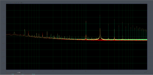
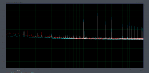
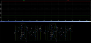
I attached two photos, comparison between the first and latest discrete designs and latest discrete and LM317+dienoiser, 44.1kHz sample rate with full FFT resolution in ARTA, 1kHz sine from phone to tda7297 amp. Around 100mA total output current and about 11.25Vout. Cyan trace is the first discrete design, yellow is LM317+dienoiser and red is the latest discrete design. The signals are bit lower than the first discrete design and a bit higher than the LM317+dienoiser. Output impedance sits the same between them so this might explain it? All three had cap multiplier in circuit while measuring. You add -60dB to the scale on the left for the real values.
I think I need to name them both.
edit: I used 2SB649AC for pass transistor for this measurement, I have no MJE15033.
The latest discrete version has a Vdrop of 0.5V across it and better performance.
I tested the latest one with a tda7297 amp and looked at the output with the 60dB LNA. I used the cap multiplier that I used on the previous LM317 boards. The cap multiplier uses a MJE15032 which is NPN and needs around 1.5V across it. But using a cap multiplier with the PNP version seems to require only 1V across it, so with the latest discrete design there would be a minimum of 1.5V across the whole thing. But it pushes to -200dB for PSRR this way.
I attached two photos, comparison between the first and latest discrete designs and latest discrete and LM317+dienoiser, 44.1kHz sample rate with full FFT resolution in ARTA, 1kHz sine from phone to tda7297 amp. Around 100mA total output current and about 11.25Vout. Cyan trace is the first discrete design, yellow is LM317+dienoiser and red is the latest discrete design. The signals are bit lower than the first discrete design and a bit higher than the LM317+dienoiser. Output impedance sits the same between them so this might explain it? All three had cap multiplier in circuit while measuring. You add -60dB to the scale on the left for the real values.
I think I need to name them both.
edit: I used 2SB649AC for pass transistor for this measurement, I have no MJE15033.
Attachments
Last edited:
Better tempco and higher current output without affecting the reference. This way there's a constant current through the reference.
I don't see any improvement here, the simulation looks the same regardless of whether it is a simple zener or GLED, GLED is designed for a voltage of 2.5V, for higher voltages there is another circuit with two transistors.
I recently did tests of WJ references with LEDs and if you follow the instructions they work great, much better than the LM329.
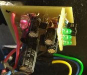
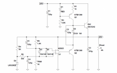
The picture shows a 19V 4A regulator that has the same input part as yours but on the bottom side of the pcb there is an AD825, GLED is a reference and is powered via CCS with 2SK246 and is set to a voltage of 6.9V, CCS holds current through GLED of about 3mA.
Attachments
There's 30nH added to the output cap ESL. If you reduce it to 20nH or even 10nH it looks better. You are talking about the 40MHz+ area?
How much ESL does a normal electrolytic cap have? Are the longer ones more inductive?
Yes indeed, I stepped the values and it smooths right out.
Most of the issues I have experienced are much lower frequency anyway.
I don't see any improvement here, the simulation looks the same regardless of whether it is a simple zener or GLED, GLED is designed for a voltage of 2.5V, for higher voltages there is another circuit with two transistors.
I recently did tests of WJ references with LEDs and if you follow the instructions they work great, much better than the LM329.
The picture shows a 19V 4A regulator that has the same input part as yours but on the bottom side of the pcb there is an AD825, GLED is a reference and is powered via CCS with 2SK246 and is set to a voltage of 6.9V, CCS holds current through GLED of about 3mA.
Maybe not so obvious for Zeners, or higher voltage Zeners, but if you try it with LEDs for lower voltages it starts to help a lot. If you look closely there's some very small improvement for Zeners as well.
Also varying output current varies the current through the voltage reference. The GLED setup shunts the extra current and keeps the reference (LED/Zener/LM329) at a fixed current irrespective of the output current.
And lastly, for high output currents there's only a certain amount of mA that can run through some references before they burn out.
Here's a comparison between without and with the GLED setup.
First photo is tempco, second is comparison of current running through one of the LEDs from each setup, with a stepped AC current load, 10mA to 100mA.
First photo is tempco, second is comparison of current running through one of the LEDs from each setup, with a stepped AC current load, 10mA to 100mA.
Attachments

In the original circuit this is not a reference position at all. Try switching it to the other side to be powered from a regulated voltage and necessarily via CCS.
Attachments
Last edited:
Yes but I used it like this as a minimum extra complication to the circuit with some extra performance and flexibility (higher output currents). I suppose it can be made more complicated with better performance, but for what it is and the fact that it can be used with simple LEDs for lower voltages for me seemed good enough.
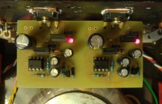
The pcb that I made also has a capacitance multiplier, doesn't take much room on the pcb anyway. Output impedance is already very low, and noise floor is either at the limits or below my measuring setup.
The supply is meant as a sort of simple and cheap fully discrete supply that can be made with accessible components.
edit:
I don't know how it was used in the Super-Reg circuit. I took inspiration from this article:
https://refsnregs.waltjung.org/GLED...D Reference Cell _Walt's Blog 2014_092418.pdf
Yes but I used it like this as a minimum extra complication to the circuit with some extra performance and flexibility (higher output currents). I suppose it can be made more complicated with better performance, but for what it is and the fact that it can be used with simple LEDs for lower voltages for me seemed good enough.
The pcb that I made also has a capacitance multiplier, doesn't take much room on the pcb anyway. Output impedance is already very low, and noise floor is either at the limits or below my measuring setup.
The supply is meant as a sort of simple and cheap fully discrete supply that can be made with accessible components.
edit:
I don't know how it was used in the Super-Reg circuit. I took inspiration from this article:
https://refsnregs.waltjung.org/GLED...D Reference Cell _Walt's Blog 2014_092418.pdf
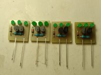
I don't know if it can be simpler than this, the AD825 can be replaced with the NE5534 or similar. It was tested on a current of 6A, the picture shows the first version with an output voltage of +/- 20V 4A in my A-class amplifier. The voltage drop is around 4V.
No problem with component selection, it works even with OS-CON and is stable.
I later made four new ones that I upgraded with Walt J. LED references and CCS.
Attachments


Last edited:
Yes but I do not want to make the Super-Reg. I am not interested in it. It's also not a full discrete design, it has an IC.
My two designs are specifically about full discrete + denoiser.
My two designs are specifically about full discrete + denoiser.
With a NE5534 I get similar PSRR, and .noise sim shows a worse noise by 5 times compared to the discrete designs. For me it's not worth it.
I could get 3A or I think 5A, can't remember, out of the discrete designs in simulation. Some transistors have to be replaced with more powerful ones but I think I might be able to make it work.
I really like the idea of simple, small part count low tech with good performance. The two discrete regulators were made to show off the simple denoiser circuit performance.
Attachments
Last edited:
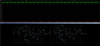
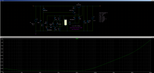
Here's 4A at 30Vout. Stepped AC load 100mA to 4A. It needs around 1.3Vdrop min at 4A. Probably could be tweaked further.
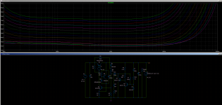
edit: added output impedance graph. The sim results are different between this and resistive loads. Why?
edit: added output impedance graph. The sim results are different between this and resistive loads. Why?
Attachments


Last edited:
@grunf -- just a methodical suggestion -- when displaying noise specify the bandwidth. Noise is always about power.
Can you clarify? It is generally normal to have an output impedance decreasing with increasing load, because dynamic impedances of semi's decrease with increasing current, but the type of load should not matter against the µ-ohm level of output impedance.The sim results are different between this and resistive loads. Why?
- Home
- Amplifiers
- Power Supplies
- D-Noizator: a magic active noise canceller to retrofit & upgrade any 317-based VReg