Hi Elvee, Diego - thanks for all the great info in this thread. Since my maths is more than rusty (and deteriorating like my eyesight for soldering....), do we have recommended starting points for R3 in the Dienoiser (as mentioned by Elvee in post #415, and Diego in posts 410 and 411) but for the LM317 for say the 5v and 15v outputs? Would they be the same as for the fixed regs LM7815 390 ohms and LM7805 1.5k ohms mentioned by Diego in #411? Thanks AdrianFor LM7805 application (low voltage than LM7815), the 390 ohms resistor should be around 1K5 ohms (according simulations).
Hello Sadface,
many thanks for your help, right now I will start by modifying an existing power supply.
Have you also tried the ZTX 851 and ZTX951?
Thanks again.
Guglielmo
many thanks for your help, right now I will start by modifying an existing power supply.
Have you also tried the ZTX 851 and ZTX951?
Thanks again.
Guglielmo
I gave a deterministic procedure somewhere above, but I am not the one who is going to carry out the math details....Hi Elvee, Diego - thanks for all the great info in this thread. Since my maths is more than rusty (and deteriorating like my eyesight for soldering....), do we have recommended starting points for R3 in the Dienoiser (as mentioned by Elvee in post #415, and Diego in posts 410 and 411) but for the LM317 for say the 5v and 15v outputs? Would they be the same as for the fixed regs LM7815 390 ohms and LM7805 1.5k ohms mentioned by Diego in #411? Thanks Adrian
If you can content yourself with an approximation, you can use this simplified relationship:
R3 = 4.3/Vout (with Vout in volts and R3 in kΩ -this will make some people cringe-)
It assumes a 1:3 current partitioning ratio, which is certainly not exact but probably sufficient unless you chase the last dB
R3 = 4.3/Vout (with Vout in volts and R3 in kΩ -this will make some people cringe-)
Example: R3 = 4.3/15v = 287 ohms
Right?
Morning,
Sorry for not going through all the threads.
Can the circuit in the first post work with LT 1083 , LT1084 and Lt 1085 regulators?
I want this regulator to power a class D amp such as TA2024 or TPA 3116.
thanks
Sorry for not going through all the threads.
Can the circuit in the first post work with LT 1083 , LT1084 and Lt 1085 regulators?
I want this regulator to power a class D amp such as TA2024 or TPA 3116.
thanks
Hi Elvee, Diego - thanks for all the great info in this thread. Since my maths is more than rusty (and deteriorating like my eyesight for soldering....), do we have recommended starting points for R3 in the Dienoiser (as mentioned by Elvee in post #415, and Diego in posts 410 and 411) but for the LM317 for say the 5v and 15v outputs? Would they be the same as for the fixed regs LM7815 390 ohms and LM7805 1.5k ohms mentioned by Diego in #411? Thanks Adrian
Attachments

Hi Elvee, Diego - thanks for all the great info in this thread. Since my maths is more than rusty (and deteriorating like my eyesight for soldering....), do we have recommended starting points for R3 in the Dienoiser (as mentioned by Elvee in post #415, and Diego in posts 410 and 411) but for the LM317 for say the 5v and 15v outputs? Would they be the same as for the fixed regs LM7815 390 ohms and LM7805 1.5k ohms mentioned by Diego in #411? Thanks Adrian
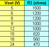
* In the schematic, R3 is the resistor without description.
Attachments
Last edited:
As a reference, to try to settle the dispute, here is a summary of the measured characteristics of the nonoiser (the Dienoiser should be very close):
Output impedance @1kHz: 15µΩ
PSRR @100Hz: 125dB raw (tweakable to 130dB)
Noise density @1kHz: 0.8nV/√Hz (With a ZTX851)
Total noise from 10Hz to 10kHz: 90nV
Ah, thanks.
The noise density could be possible.
I can't do anything at the moment because my FFT analyzer
drops from the LAN every few seconds. It used to happen
now and then, but with the newest Linux kernel updates it
is essentially unusable. Trying to go the GPIB route was
harder than expected, not yet finished.
Bravo Diego...!!!
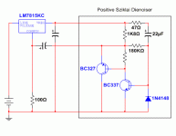
Why have you shifted the 47R resistor in series with the output,rather than its protection role for the npn BJT?
Is it not needed anymore for fixed regs.? Less noise?
Why have you shifted the 47R resistor in series with the output,rather than its protection role for the npn BJT?
Is it not needed anymore for fixed regs.? Less noise?
I think some members have tested it with LT1086 or 1084; anyway, it works in sim, but that's no guarantee.Morning,
Sorry for not going through all the threads.
Can the circuit in the first post work with LT 1083 , LT1084 and Lt 1085 regulators?
I want this regulator to power a class D amp such as TA2024 or TPA 3116.
thanks
Especially for other types than the LM317, you should use the updated circuit given somewhere before: the one with a 22nF compensation cap.
The larger cap slightly blunts the HF performance, but improves the stability to make it compatible with other types of regulators, including negative ones.
That said, using such a reg to power a class D amp is overkill, but since it is cheap, why not
It's interesting.
I could find some ZTX851 and ZTX951 models to try, both on Elvee's Denoiser and on Diego's, and noise did get reduced on both simulations.
I haven't yet checked if they influence anything else.
Note the regulator is the LT317.
I could find some ZTX851 and ZTX951 models to try, both on Elvee's Denoiser and on Diego's, and noise did get reduced on both simulations.
I haven't yet checked if they influence anything else.
Note the regulator is the LT317.
Attachments
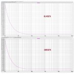
In practice, the transistor type is not going to influence the final noise of the denoiser: it has an insufficient gain to eliminate completely the 317's noise, unlike the Dienoiser or the nonoiser, and this noise will dominate in reality.
The sim shows an improvement only because of the simplified, noiseless LT317 model.
The sim shows an improvement only because of the simplified, noiseless LT317 model.
Bravo Diego...!!!
Why have you shifted the 47R resistor in series with the output,rather than its protection role for the npn BJT?
Is it not needed anymore for fixed regs.? Less noise?
Removing the 47 ohm resistor was only a suggestion to vacuphile in order to carry out a quick and dirty test.
The use of this resistor is convenient (even better at lower values), for when the regulator output is accidentally short-circuited, avoiding damaging the base-to-emitter junction of the NPN transistor.
This same resistor reduces performance a bit.
Best regards
R3 values
Thanks Elvee, and Diego for the table of values! Saved me a lot of head scratching.....
Thanks Elvee, and Diego for the table of values! Saved me a lot of head scratching.....
It is time to take stock, and review all the options and variants offered in this thread, because it is slowly becoming a large, disorganized mess where newcomers have difficulty finding pertinent information.
The X-noisers come in three main flavors:
These X-noisers are only usable with a standard regulator implementation, with or without additional caps. They are not compatible with current boosters, or circuits already including an enhancement amplifier.
The original regulator should already include normal bypass caps, input and output.
The input cap is preferably a low-esr type, and can be very low esr, the output cap is a standard or low-esr E-cap, but it cannot be an ultra-low esr type, like solid polymer.
Parallelling different types of capacitors should be avoided at all costs, since it creates nasty resonances leading to instability.
A sensible layout is also important: it makes no sense to add a X-noiser to a circuit corrupted by ripple for example.
For the denoiser, the components are relatively unimportant: the transistor can be an ordinary, medium power type like the BC337.
For the Dienoiser and the nonoiser, using a low Rbb type like the ZTX851 is beneficial if you are after the ultimate noise performance.
With a good implementation, an improvement of >30dB for all key parameters can be gained with the denoiser: PSRR, output impedance and noise (compared to a cap-equipped 317).
This rises to >50dB for the Dienoiser and the nonoiser. The ultimate noise performance will also be limited by the input transistor: about 0.8nV/VHz with a ZTX851.
For the Die-and no-noiser, the layout is very important, and should be Kelvin-like even if the final output is on two wires.
Various measurements results and curves can be found here and there in the thread, some from myself, some from other members.
The X-noisers come in three main flavors:
- The denoiser is the original implementation; it is the simplest, cheapest and most universal, and it is also retrofittable.
It offers the best bang for buck, with a 30~35dB improvement on all key parameters.
Since it is universal, it is possible to build in advance a stock of ready-to-use add-on boards, and fit them according to the needs.
It will work from 3 to 30V.
Something to keep in mind: it ~doubles the quiescent current of the 317.
The up-to-date version is this one:
It could in principle be adapted to other 3-pin regulators types, but some mods might be required, like an increased compensation capacitor value, or a small series resistance with this cap.
It also works with the LM337 (with all the polarities reversed, of course)
- - The Dienoiser has one more transistor, and improves the performances by another ~20dB.
It is also retrofittable, at least in principle, but if the original layout has not been thought with ultra-high performance in mind, it will not be possible to achieve the full benefits.
In practice, for retrofitting purposes, the denoiser remains the best option.
The Dienoiser is not completely universal: resistor R3 needs to be adapted to the output voltage.
Here is a table giving the resistor's value for various voltages:
D-Noizator: a magic active noise canceller to retrofit & upgrade any 317-based V.Reg.
Like the denoiser, the Dienoiser also doubles the quiescent current.
- - The nonoiser is slightly more complex, and has performances similar to the Dienoiser, but it also offers some advantages.
It allows more convenient capacitor values, meaning the 220µF can be reduced if desired, or kept identical to improve the VLF response: wider and no peaking.
Another advantage is that the quiescent current is not increased compared to a simple regulator.
The voltage formula is not exactly that of a 317; it can be found here:
D-Noizator: a magic active noise canceller to retrofit & upgrade any 317-based V.Reg.
These X-noisers are only usable with a standard regulator implementation, with or without additional caps. They are not compatible with current boosters, or circuits already including an enhancement amplifier.
The original regulator should already include normal bypass caps, input and output.
The input cap is preferably a low-esr type, and can be very low esr, the output cap is a standard or low-esr E-cap, but it cannot be an ultra-low esr type, like solid polymer.
Parallelling different types of capacitors should be avoided at all costs, since it creates nasty resonances leading to instability.
A sensible layout is also important: it makes no sense to add a X-noiser to a circuit corrupted by ripple for example.
For the denoiser, the components are relatively unimportant: the transistor can be an ordinary, medium power type like the BC337.
For the Dienoiser and the nonoiser, using a low Rbb type like the ZTX851 is beneficial if you are after the ultimate noise performance.
With a good implementation, an improvement of >30dB for all key parameters can be gained with the denoiser: PSRR, output impedance and noise (compared to a cap-equipped 317).
This rises to >50dB for the Dienoiser and the nonoiser. The ultimate noise performance will also be limited by the input transistor: about 0.8nV/VHz with a ZTX851.
For the Die-and no-noiser, the layout is very important, and should be Kelvin-like even if the final output is on two wires.
Various measurements results and curves can be found here and there in the thread, some from myself, some from other members.
Last edited:

- Something to keep in mind: it ~doubles the quiescent current of the 317.
AND:
When retrofitting , be sure to check whether there are ceramic caps at the output , it will make it unstable especially with the LM337.
Adjusting R1 & R4 you adjust the output voltage, not the quiescent current.
AFAIK there's nothing on the datasheet that mentions you can do that, like keeping R1-R4 ratio but doubling their value, for instance. That doing that you can decrease the quiescent current.
AFAIK there's nothing on the datasheet that mentions you can do that, like keeping R1-R4 ratio but doubling their value, for instance. That doing that you can decrease the quiescent current.
^ R1 in the above Elvee DeNoiser post 537 , sets the current of the LM regulator, R2 sets the output voltage. ( of course by changing the current through R1 , you change the output voltage too). R1 can be between 100 and 1k2 , setting the current from 12,5mA to about 1 mA. The real quiescent current of the LM itself is the 50-60 uA out of the adj pin.
R4 has nothing to do with R1/R2 .
If you read all the 500+ posts , you would know that this was my (very small) contribution to this thread : lowering the quiescent current of the DeNoiser for battery or mixed applications.
Elvee uses 220 and 1k8 which takes about 11-12 mA for a 15 V output , I use 360 and 3k6, and 390k for R5 , so around 6 mA depending on your transistor's Vce.
The LM+DN doesn't have to consume more than the LM alone.
- Home
- Amplifiers
- Power Supplies
- D-Noizator: a magic active noise canceller to retrofit & upgrade any 317-based VReg