That is a much more interesting proposition: the CFP improves the gain/impedance of the correction amplifier by ~20dB, meaning an equivalent effect on PSRR, noise reduction and output impedance.
If it works in reality, it could be an intermediate alternative between the denoiser and the nonoiser.
The question is: how will it behave, what will it need for compensation?
For the nonoiser, I had to switch to a series inductance for an acceptable result, but I have no idea about the behavior of the CFP.
Sim does not show anything, but it is basically useless in this case: it has to be tested in the real world, preferably with various operating conditions and 317 samples.
Anyway, it is something worth investigating. Bravo Diego!
Yesterday i was measuring noise of d-noiser and comparing it to normal lm317 cap on adj pin regulator and i got interesting measurement.
LNA and battery pack are grounded in only one point, at HP334a input connector. Ground and earth connectors of HP334a are shorted, BUT when i connect shield of LNA with chassis readings on voltmeter drop from 115uV to 65uV??? I would say that is a bit too good noise level, i'm using BC550(hfe 500) and i know bc337 is less noisy then bc550 so i'm a bit puzzled with this.
Since LNA has x100 gain that means i get 1,15uV and 0,65uV measurement.
Since your LNA bandwidth is 20kHz, the noise density would be around 4.6nV/√Hz, which is perfectly plausible.
With low-level measurements, ground-related issues are a constant worry.
I try to use as many class II instruments as possible, as it removes a major source of troubles, but even so, the tens of µA leakage currents circulating in the shields and ground connections are sometimes sufficient to be problematic.
You have to use the configuration that gives the best result, 0.65µV in your case, and I advise you make as many sanity checks as possible.
First, with the regulator under test completely disconnected from the mains (plug pulled) and your normal configuration of instruments, measure the level with the output of the regulator shorted.
Then, connect your regulator to the mains (plug inserted), but switched off and measure the level again. Do you see a difference?
Then, with the regulator plugged in and energized, connect the shorted input of the LNA to the GND of the regulator. Difference again?
In principle, all those measurements should give the same result, the noise floor of your LNA. If it isn't the case, investigate, visualize the 334 output on an oscilloscope, listen to it: the ear can detect a buzz drowned in noise
I have made a quick, simplified breadboard test of Diego's version, let's call it the Dienoiser, and it seems to work perfectly.
Of course, a more complete assessment would be required, to investigate stability aspects in particular, but it is certainly possible to make it work.
The compensation needs to be somewhat larger than for the simple Denoiser, it oscillates with C<6nF, but 22nF seems a good starting value.
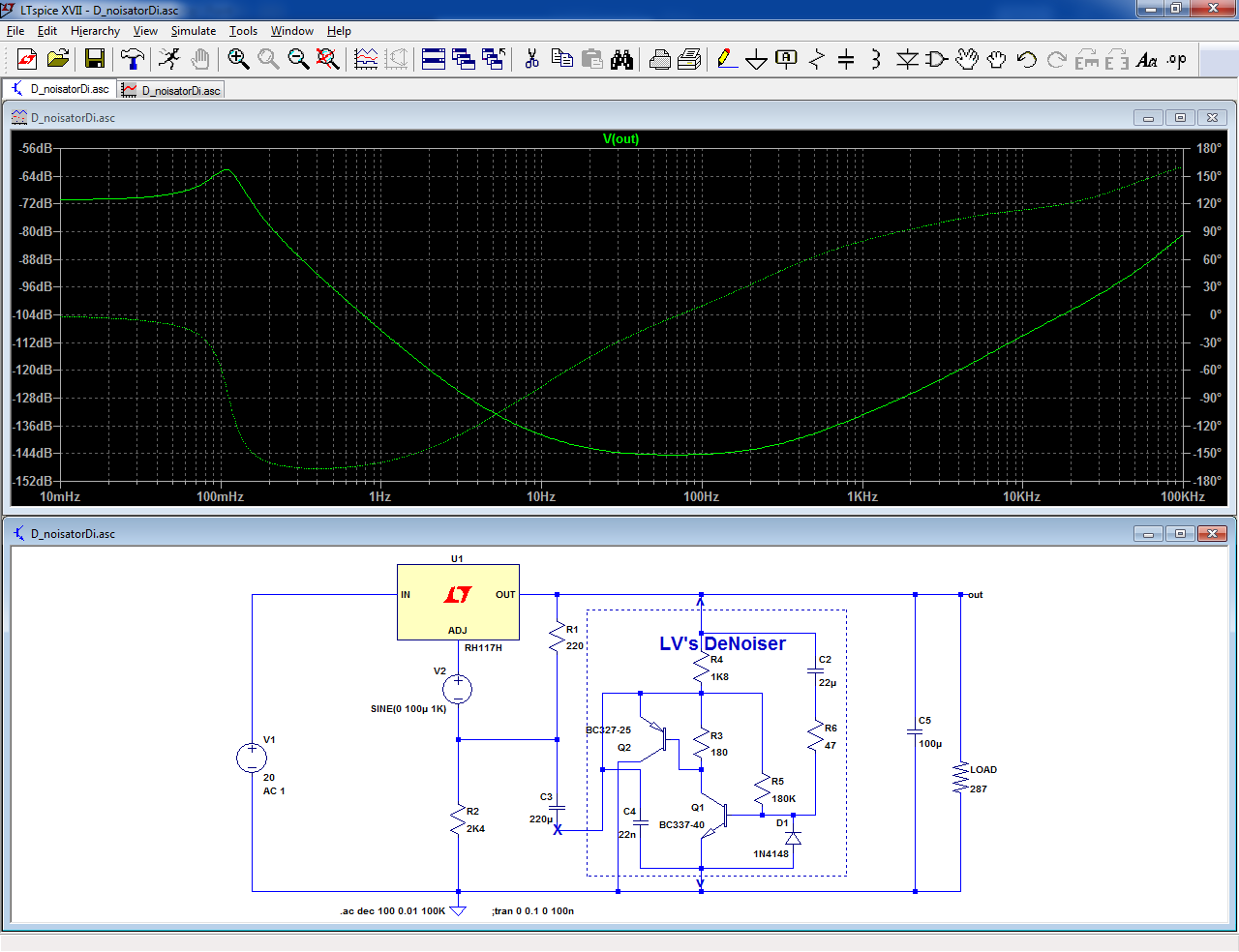
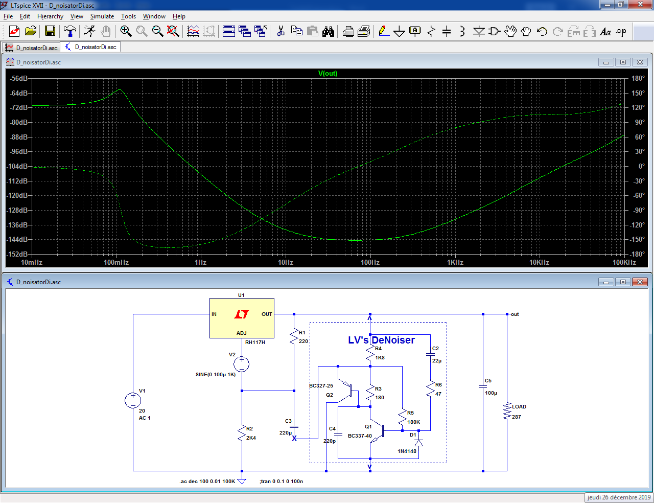
It is also possible to use an alternate compensation scheme, with a 220pF capacitor:
The Dienoiser has interesting specificities compared to the nonoiser and denoiser, and offers an additional 20dB overall performance compared to the denoiser
Of course, a more complete assessment would be required, to investigate stability aspects in particular, but it is certainly possible to make it work.
The compensation needs to be somewhat larger than for the simple Denoiser, it oscillates with C<6nF, but 22nF seems a good starting value.
It is also possible to use an alternate compensation scheme, with a 220pF capacitor:
The Dienoiser has interesting specificities compared to the nonoiser and denoiser, and offers an additional 20dB overall performance compared to the denoiser
Attachments
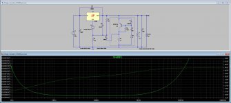
At a specific value of R3, the rejection of ripple is maximized. The first test value of 180 ohms gives acceptable results, although with values close to 390 ohms we would obtain the highest PSRR in the 100 Hz range. Complementarily, some compensation capacity must be modified.
According to my simulator (Multisim 14), the biggest rejection would be in the order of 135 dB at 100 Hz, although I am observing even higher PSRR in LTSpice with only first test value of 180 ohms.
I like very much this Dienoiser!!! 😀
Best regards
According to my simulator (Multisim 14), the biggest rejection would be in the order of 135 dB at 100 Hz, although I am observing even higher PSRR in LTSpice with only first test value of 180 ohms.
I like very much this Dienoiser!!! 😀
Best regards
Attachments
Last edited:
R3 is probably one of the most critical component of the Dienoiser: it heavily influences the performance, and it is output-voltage-specific.
In principle, a Dienoiser could be used as an upgrade for a regular 317 regulator, just like the denoiser, but R3's value will have to match the output voltage, which is a minor inconvenient considering the performance.
What the simulations predict has to be taken with a pinch of salt, because at the level reached, many minor effects are not taken into account.
What can reliably be said is that a denoiser adds >30dB of performance to a SOTA, cap-fitted 317 regulator, and the Dienoiser adds ~20dB on top of that, resulting in a 50~55dB global improvement for PSRR, impedance and noise.
Of course, the noise performance will be reachable only if the input transistor has a sufficiently good intrinsic noise performance
Do you really think that difference will be audible?What can reliably be said is that a denoiser adds >30dB of performance to a SOTA, cap-fitted 317 regulator, and the Dienoiser adds ~20dB on top of that, resulting in a 50~55dB global improvement for PSRR, impedance and noise.
It very much depends on the actual use: for line-level circuits using decent audio opamps, probably not unless there is some serious design flaw, but for a discrete ribbon mic preamp having a PSRR of ~0dB, it might not even be sufficient: you could need additional passive filtering on top of the ~130dB rejection
Other magic application: Fixed Regulators!!!
Compensation not shown.
The values of the electrolytic capacitors not displayed may differ depending on the type of regulator. They could result in higher values compared to those required for the LM317.
Compensation not shown.
The values of the electrolytic capacitors not displayed may differ depending on the type of regulator. They could result in higher values compared to those required for the LM317.
Attachments

Last edited:
For LM7805 application (low voltage than LM7815), the 390 ohms resistor should be around 1K5 ohms (according simulations).
Interesting. As I do not have RH117 or LM317 models available on my LTSpice, I keep using the closest ones, which are LT1083 and LT1085.
They reach only -134dB @ 100Hz, instead of -144dB.
Is there a completely reliable model to use for the regulator?
Another question: why the curves you get with 22n and 220pF are exactly the same? Shouldn't they be slightly different?
Now about R3: how do you select the right value? By trying and error?
Attachments
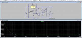
OK, I took the liberty of trying to simulate the output impedance from Diego's Dienoiser, and the results are absolutely remarkable.
Please check the asc file and tell me if the results I get are real.
I will later carry on those tests with the first Diego Denoiser version.
Please check the asc file and tell me if the results I get are real.
I will later carry on those tests with the first Diego Denoiser version.
Attachments

Thank you Elvee, Diego and Carlos! Having fun with the sims, really impressive! This is going to be very useful.
Tomorrow I will start soldering something together with BC549C and BC560C. How to measure this stuff will be a challenge, though. If anything useful comes out I will report.
Tomorrow I will start soldering something together with BC549C and BC560C. How to measure this stuff will be a challenge, though. If anything useful comes out I will report.
Other magic application: Fixed Regulators!!!

Wonderful!!! Santa Claus has done it again, just as he did exactly one year ago!

DIYers now have a flurry of x-noisers to chose from!
They are slightly different, but their effect is calculated to be identical: 22n/0.22n~= βAnother question: why the curves you get with 22n and 220pF are exactly the same? Shouldn't they be slightly different?
You simply have to write down the gain equation of the correcting amplifier loaded by the voltage setting network, take the derivative with R3 as variable, and compute the value of R3 for which this derivative is zero.Now about R3: how do you select the right value? By trying and error?
I leave the honour of computing the optimum R3 value to Diego, as he is the creator of this version 😀
(BTW, my maths are ~45 years old, and a bit rusty)
You should have taken my advice into account:Here are the impedance results from the first Diego Denoiser mod, which I find quite remarkable.
The asc file is also included, to check if the parameters I used are OK.
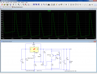
This is the transient analysis (it is not needed in fact, because a simple inspection of the schematic shows that the phase of the correction is reversed):Nice idea, but even if you don't want to get into hardware, I advise you to make a transient simulation: the result will surprise you....
Attachments
You should have taken my advice into account:
Which of them all?
Why don't you use some asc file, mine or yours, and upload the impedance curve you get?
Now what about noise? I activated the noise parameters and got two curves from both Diego supplies.
Both look the same, but the more recent version has a 4.5nV peak at 1MHz.
Attachments

The one I gave to Diego:Which of them all?
He was sensible enough to follow itNice idea, but even if you don't want to get into hardware, I advise you to make a transient simulation: the result will surprise you....
Because it makes no sense: the circuit is non-functional (as a regulator anyway, but it works as a VLF multivibrator)Why don't you use some asc file, mine or yours, and upload the impedance curve you get?
The one-transistor version is to be discarded.Now what about noise? I activated the noise parameters and got two curves from both Diego supplies.
Both look the same, but the more recent version has a 4.5nV peak at 1MHz.
The peak on the functional one is probably caused by the compensation: either it is inadequate, with a too small phase margin and a resonance, or it is too aggressive and lets some noise in when the correction runs out of steam.
The two are not mutually exclusive, and it might be impossible to find a good trade-off with a simple compensation scheme like this one
Should the correct result from a transient simulation be a straight line at the output voltage?
Yes, of course but even that will not always prevent silly mistakes: if the simulation time is too short to show VLF oscillations, or if the timestep is too large to allow oscillations to appear, you might see the correct voltage, or some strange voltages and behavior, without oscillations.
Simulations are useful tools, but they are no substitute for common sense or judgement.
Any circuit should pass these first sanity checks before it is simulated, and in the simulation, you need to know what you are looking for: in an AC analysis, if the sim is not specifically configured to look for instability you will miss it, even it is elephant-size.
With a physical circuit, you have inherent sanity checks, even if you haven't prepared anything: magic smoke, etc.
Hello,
thank you Elvee for this nice and simple circuit.
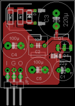
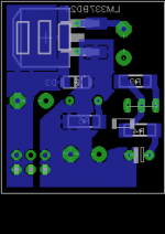
I made a PCB for Denoizator (pos and neg) and have some questions about the layout. Attached is the negative version.
PCB size and especially connector placement is quite fixed, I designed it for a specific amplifier with 3pin-connection (Input-GND-Output) to the motherboard.
The D2PAK package of the LM337/317 is chosen on purpose to minimize footprint and prevent the LM317/337 tabs to just dangle in free air (reducing risk of shorting inputs or outputs when tinkering). Current consumption of the amplifier circuit is below 10 mA, so I think I can get away with the quite small amount of copper trace acting as heatsink.
Layout questions: Beside general remarks for improvement, I am not sure how to connect the grounds of the circuit. Maybe it doesn´t really matter, and eventually it is somewhat philosophical considering that is not really a high frequency circuit. Should I use a ground-plane (as shown in red; larger?), a star ground (meeting at the output connector), or some other functional arrangement? Comments are welcome.
Thank you,
Florian
thank you Elvee for this nice and simple circuit.
I made a PCB for Denoizator (pos and neg) and have some questions about the layout. Attached is the negative version.
PCB size and especially connector placement is quite fixed, I designed it for a specific amplifier with 3pin-connection (Input-GND-Output) to the motherboard.
The D2PAK package of the LM337/317 is chosen on purpose to minimize footprint and prevent the LM317/337 tabs to just dangle in free air (reducing risk of shorting inputs or outputs when tinkering). Current consumption of the amplifier circuit is below 10 mA, so I think I can get away with the quite small amount of copper trace acting as heatsink.
Layout questions: Beside general remarks for improvement, I am not sure how to connect the grounds of the circuit. Maybe it doesn´t really matter, and eventually it is somewhat philosophical considering that is not really a high frequency circuit. Should I use a ground-plane (as shown in red; larger?), a star ground (meeting at the output connector), or some other functional arrangement? Comments are welcome.
Thank you,
Florian
Attachments

Last edited:
- Home
- Amplifiers
- Power Supplies
- D-Noizator: a magic active noise canceller to retrofit & upgrade any 317-based VReg