Great.
Now I understand the need of a PNP instead of a NPN as in the first simulation.
I did not see the wrong phasing and it did not occur to me that changing from NPN to PNP would invert the phase.
Thanks for the 32V output ( iso 10V).
I think you forgot the 100uF cap at the output. The stability issue is not the same.
Have you seen a stability improvement thanks to adding C1 10 nF ?
You add R7 C4. A compensation for stability, I presume, why these values 22 nF 33R.
About the R C at the transistor base,
Same C 22uF but R changed from 33 to 22, any reason or it doesn't matter ?
About a PSU for higher current. Q1.
A Slizar has this advantage over a Darlington: The TL431 biasing resistor ( 2K in the simulation ) can be larger for the same unregulated voltage droop. I bias must be > 1mA.
This advantage is only 0.7V, but may be good to have to face unregulated droop and higher ripple at high current draw.
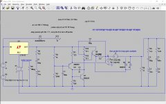
Output capacitor was deliberately left out for simulation. This regulator is not as prone to instability as the complex IC regulators. Transient simulation didn’t show any instability. In the real circuit, there will be some output capacitor, but adding one from 10 uF to 100 uF didn’t’ change circuit behavior.
C1 is something LT431 application note has, so I added it. No big changes in the simulation but I expect it to be important in the actual circuit.
R7 & C4 are prevention from high frequency oscillation, just with so far determined usual values. There should be some adjusting and with real prototype circuit.
R5 was decreased to 22R as it’s noise (higher with R value) is affecting circuit noise density which is, using ZTX transistor at extremely low level. For audio purposes, I deem that BC327-40 and 33 R will be overboard.
I’m also in favor of Sziklai pair as Q1.
Thanks for your fast and accurate answers.
Shame on me, about what I said about R7 C4.
I oversaw that C4 is simply moved to follow the change from NPN to PNP.
I understood the reason for C4 in the original Elvee circuit.
The only thing added is R7 33 ohm. Why ?
May be explained early in the thread where C4 is explained.
Edit: It says, C4 should be > 3.3nF. There is no real benefit to make it smaller, 10nF or 22nF makes the circuit more tolerant to component variations and stray parasitics.
A great thing is: You confirm good stability.
Could this be checked to know about phase margin. ( Middlebrook, Tian method ).
Last edited:
This thread is very long and contains wealth of useful information. It is worth to be read from the beginning.
Regarding stability, keep in mind that those simulation are simplified and no absolute warranty. There could be some adjustments with the real circuit but this regulator will work. I prefer this to LM317 + denoiser.
As for the further analysis, it’s not fair to others that only I have fun 🙂
Regarding stability, keep in mind that those simulation are simplified and no absolute warranty. There could be some adjustments with the real circuit but this regulator will work. I prefer this to LM317 + denoiser.
As for the further analysis, it’s not fair to others that only I have fun 🙂
It might be better to create a new thread dedicated to the TL431 solution.
I do not want to hijack the Elvee's D noizator thread and bring confusion with LM317.
What do you think ?
I do not want to hijack the Elvee's D noizator thread and bring confusion with LM317.
What do you think ?
maybe you can pm him and see what he thinks. I actually like all the information in one thread instead of spreading out over many threads.
This thread is about denoiser circuit in its’ various variants, not only with the LM317/LM337.
Seems to be the right place. Elvee will have definitive word in the matter if this would be better as separate thread but we should not burden him ATM.
Seems to be the right place. Elvee will have definitive word in the matter if this would be better as separate thread but we should not burden him ATM.
A possible upgrade is replacing R1 by a CCS, I do not know wether this is worthwhile.
A CCS made of 2 transistors and 2 resistors.
Or a LM334 and 1 resistor.
ATL431 is same as TL431 with better caracteristics at very little extra cost.
Complementary TL431 doesn't exist, so there is no way to make a negative voltage PSU, the exact mirror of the positive one.
The consequence is for a +V 0 -V PSU; One cannot simply use a center tap transformer with a diode bridge.
To go around this, one must use a transformer with two independent secondary windings and two diode bridges to feed two identical regulators.
I do not know wether there is a drawback to do so.
The trouble comes from Vref of the TL431 referenced to the anode. It comes handy for a positive voltage regulator.
Not so for a negative voltage regulator. Here one can implement a quasi mirror, configuring the TL431 to simply make a Zener, this works, but downgrades the load regulation.
Is there a trick, a better workaround ?
Last edited:
I had posted negative regulators using TL431 in the other thread.
LM317+TL431, really?
This circuit is similar topology to LM337, 100%NFB+PFB to set the output voltage.
...and another circuit with LM317
LM317+TL431, really?
This circuit is similar topology to LM337, 100%NFB+PFB to set the output voltage.
...and another circuit with LM317
Attachments
I understand you make a module that has 3 terminals: A, Ref, K.
This module can replace a TL431 in an existing circuit ?
I do not see how this work.
Can you make it clear on the schematic ?
This module can replace a TL431 in an existing circuit ?
I do not see how this work.
Can you make it clear on the schematic ?
Tombo56,
I simulated your schematics from post 1040.
I need the 100uF at the output for stability with a small series resistor ( as a real cap ).
I get a great improvement, replacing R1, 1K by a 4mA constant current.
-162 dB rejection at 100 Hz
-143 dB at 1 KHz
-117 dB at 20 KHz.
C1 10nF is important about stability
Lower gives better rejection, but not safe.
I have played with other component values, they seem optimum.
R7 33 ohm, seems useless, I removed it.
I understand you make a module that has 3 terminals: A, Ref, K.
This module can replace a TL431 in an existing circuit ?
I do not see how this work.
Can you make it clear on the schematic ?
Here on the left is a standard 5V TL431 shunt regulator/reference from the datasheet. On the right is the denoised version. The dashed rectangle contains the module to replace TL431.
Attachments

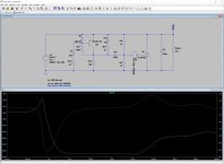
Not every simulation containing same components is the same. It depends on models used and additional component parameters. LTSpice simulation is very useful but only real test circuit gives definitive answers. Just add small inductance between all components connection points, representing pcb traces and small cross capacitances and there will be different situation.
I checked stability (not very extensively) at the beginning and it was OK. Checking again, I have different outcomes, some with big output oscillation.
If I leave C1 in place and no output capacitor, output oscillates after 30 mS and on. With no C1 and no output capacitor, output is stable in 2 minutes long transient analysis.
With C1 in the position and output capacitor, output oscillates after 60 mS if capacitor ESR is high (500 mΩ), but is stable with 220 and 50 mΩ.
Without C1, output is stable with whatever output capacitor ESR.
So, seems that C1 is better to be omitted and it ruins PSRR at high frequency, especially if you add Darlington or Sziklai instead of Q1. Anyway, I don’t find this capacitor in the actual implementations.
R7 changes phase response at high frequency. Check 22 nF and 33Ω and then with 10Ω and see how phase response “bends” and stays below 180°.
Without C4 regulator oscillates.
Regarding CCS instead R1, it’s great that there is a big improvement.
Again, this circuit can be insanely good adjustable voltage reference, packed at small PCB with SMD components that is retrofittable to existing circuits or a complete standalone regulator.
Here on the left is a standard 5V TL431 shunt regulator/reference from the datasheet. On the right is the denoised version. The dashed rectangle contains the module to replace TL431.
Note that the TL431 shunt regulator/reference needs some additional power supply series resistance (or typically a separate series resistor) to work properly. The 1 ohm shown in these simulations is too low.
Indeed, your module is not a 3 pins replacement for a TL431.
Furthermore, there is no need to replace the TL431 of the modified hardware by the one inside your module.
The thing that might be worthwhile for a mod at a TL431 is what's on your module without it's TL431.
Furthermore, there is no need to replace the TL431 of the modified hardware by the one inside your module.
The thing that might be worthwhile for a mod at a TL431 is what's on your module without it's TL431.
Indeed, your module is not a 3 pins replacement for a TL431.
Like I said my module is a low-noise replacement of TL431 in low-current shunt regulators/references. Not universal replacement.
Furthermore, there is no need to replace the TL431 of the modified hardware by the one inside your module.
The thing that might be worthwhile for a mod at a TL431 is what's on your module without it's TL431.
What do you mean by this? Why is it not worthwhile to replace TL431 with something having lower noise?
I mean, the Elvee' s denoiser module is fine for an add on to a TL431, with no need to change it.
Elvee's denoiser has 3 terminals:
1 Ground
2 In supply voltage
3 out to the device under denoizing.
Simulations, in previous posts, show clearly how an Elvee denoiser is added at the TL431 used in a PSU.
"Replacement" of TL431 is ambiguous and an inappropriate word here. May be a language misunderstanding.
Last edited:
I mean, the Elvee' s denoiser module is fine for an add on to a TL431, with no need to change it.
You seem to be missing the point. Even if TL431 is included in the TL431-denoiser add-on PCB, you can always leave it unstuffed and use your TL431-denoiser without it. Adding TL431 to the module makes it more universal since it can be used as a direct low-noise TL431 replacement in shunt regulators/references.
This looks like a commercial rip off to me.
It makes no sense to change the TL431 in shunt regulators/references, the thing that makes sense is adding a denoiser.
All I see is snake oil vendor argumentation.
It makes no sense to change the TL431 in shunt regulators/references, the thing that makes sense is adding a denoiser.
All I see is snake oil vendor argumentation.
Last edited:
- Home
- Amplifiers
- Power Supplies
- D-Noizator: a magic active noise canceller to retrofit & upgrade any 317-based VReg