thanks for gerbers
which Is reason of using a sziklai pair Instead off one transistor
what Is output voltage range - can we use It for + 5 Vdc and - 5 Vdc
do you have a BOM
which Is reason of using a sziklai pair Instead off one transistor
what Is output voltage range - can we use It for + 5 Vdc and - 5 Vdc
do you have a BOM
While adding LED pilot indicator my brain decided, without notifying me, that LED diode should be reversed polarity like Zenner diode. Today, some leftover brain cell kicked in and I spotted mistake.
If anyone ordered the pcbs it’s no big deal. Just mount LED in reverse to markings on the silkscreen. Corrected gerbers in attachment. Sorry for any inconvenience.
Last edited:
thanks for gerbers
which Is reason of using a shikazi pair Instead off one transistor
what Is output voltage range - can we use It for + 5 Vdc and - 5 Vdc
do you have a BOM
That was an improved noise kill version to the original Denoiser, and it was called Dienoiser, because of Diego, the designer.
On simulation, Dienoiser specs are considerably better than the Denoiser.
In any case both are superb designs.
thanks for gerbers
do you have a BOM
...Only a few pages behind.
https://www.diyaudio.com/forums/pow...fit-upgrade-317-based-reg-17.html#post6235992
thanks for gerbers
which Is reason of using a sziklai pair Instead off one transistor
what Is output voltage range - can we use It for + 5 Vdc and - 5 Vdc
do you have a BOM
Yes, it can work very well for the 5V output voltage with some component values adjustments.
At first, my design was not intended to become public but one form member was in search for a single rail design. I really recommend Mark Johnson’s VRDN project as it is professionally made up to highest DIY standards and contains BOM and building instructions.
VRDN: bipolar regulator PCB for line level ckts: ±11V to ±20V @ 1.5A with "De-Noiser"
For dienoiser version, BOM is dependent on output voltage and current. If you really intend to build this PS, I can prepare tailored BOM for 5V / ?? mA.
Hi Elvee, thank you for your project.
A slightly off piste question if I may, could I use this power supply to power the TM3B meter?
I have just restored and recapped one and would like to put a little regulator into a pp3 battery case and feed it with a 12v dc wall wart.
Would this supply be quiet enough, or possibly even quieter than the battery if I have followed correctly?
I also have a TM3, and I converted it a very long time ago.
I don't remember exactly how I did it, but it was certainly cruder than a denoiser.
Probably a 317, maybe with the help of some passive filtering, but certainly nothing extraordinary.
Levell instruments were cheap, but quite well made, and the supply doesn't matter too much.
Anyway, no 100Hz hum is visible in the monitoring output.
The noise floor is not exceptional, and I had to make my own LNA to really evaluate the denoiser.
That said, a denoiser is certainly not quieter than a battery, and a mains supply brings other problems, like the magnetic field leaked by the transformer, or the µA's leaked by the transformer's capacitance (or the Y caps, if you use a SMPS).
µA don't look like a problem, but in very low noise setups, the voltage developped across the ~0.1ohm of the GND connections can become a headache, and a battery is the ideal solution.
IIRC, the original battery size was totally inconvenient, which is why I converted it
Thanks for the reply Elvee.
I was hoping to avoid transformer related leakage by housing the ground-up version of the denoiser in a PP9 battery box ( the inconvenient to obtain one) and housing the transformer at the wall plug end by using a 12v DC plug in linear regulator type supply.
I'm not too worried about getting LNA levels of performance, it's a nice piece of vintage test gear that slots in with my other vintage gear.")
I am a newbie in this hobby and all advice is gratefully accepted.
If I can ask a question on testing, did you run a capacitor in series with the TM3B input and if so what size?
I notice you bandwidth limited for your tests, mine has a 10hz to 350hz range in addition to those on yours, what sort of range would be the most reasonable for audio power supply noise measurement at this primitive level? Would this be different for measuring SMPS or linear power supply noise?
I was hoping to avoid transformer related leakage by housing the ground-up version of the denoiser in a PP9 battery box ( the inconvenient to obtain one) and housing the transformer at the wall plug end by using a 12v DC plug in linear regulator type supply.
I'm not too worried about getting LNA levels of performance, it's a nice piece of vintage test gear that slots in with my other vintage gear.
I am a newbie in this hobby and all advice is gratefully accepted.
If I can ask a question on testing, did you run a capacitor in series with the TM3B input and if so what size?
I notice you bandwidth limited for your tests, mine has a 10hz to 350hz range in addition to those on yours, what sort of range would be the most reasonable for audio power supply noise measurement at this primitive level? Would this be different for measuring SMPS or linear power supply noise?
A wall-wart is inelegant, but it is by far the safest and simplest method.Thanks for the reply Elvee.
I was hoping to avoid transformer related leakage by housing the ground-up version of the denoiser in a PP9 battery box ( the inconvenient to obtain one) and housing the transformer at the wall plug end by using a 12v DC plug in linear regulator type supply.
With a denoiser inside the box, the supply noise will be totally negligible
It already includes one: it is an AC-coupled instrument.If I can ask a question on testing, did you run a capacitor in series with the TM3B input and if so what size?
You would need to add one if you work on very high voltage tube circuits, but for normal, semiconductor use, the internal one is sufficient (and it is well shielded).
IIRC, the capacitor has a 400V rating
In principle, for general audio work you need an ~audio bandwidth, but to analyze specifically power supplies, a more limited range like 10 - 350Hz makes sense: That's where most of the noise is, and even if higher frequency noise is present, it matters less, because preamps etc. include some basic supply filtering, effective at high frequencies.I notice you bandwidth limited for your tests, mine has a 10hz to 350hz range in addition to those on yours, what sort of range would be the most reasonable for audio power supply noise measurement at this primitive level? Would this be different for measuring SMPS or linear power supply noise?
With SMPS, the sheer level of crap can cause whizzing and whistling even if the switching frequency is ultrasonic, because of intermodulation, and measuring a wider range makes sense
I Intend to try out for supplying dac chips, so 5V 50 - 100 mA
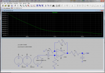
am I correct to think that R2 set current and RV1 output voltage
RV sets output voltage. R2 is part of RC filter and it’s value should be as high as possible but maintaining reasonable voltage drop and dissipated power.
BOM with values optimized for 5V output is in the attachment. According to the LTSpice simulation, with these values regulator achieves over 140 dB PSSR (surely somewhat less in practice).
Optimal dienioser values are different for various output voltages. With BC transistors, output noise level could be less than 0,5 µV and with ZTX ones less than 0,1 µV. Output impedance is in range of µ ohms.
Suggested part numbers in the BOM list are by no means exclusively acceptable or best possible. The most critical part is C8. It has to have ESR in certain range. To low or to high value and regulator could oscillate. That’s why there is a position for resistor in series with C8 so ESR can be adjusted and it is possible to use long life, low ESR, big value capacitors.
We all would very welcome your input on how does this regulator sonically compare to Salas shunt regulators and other types. IIRC you have build your own version of shunt regulators and some other types.
Attachments
A wall-wart is inelegant, but it is by far the safest and simplest method.
With a denoiser inside the box, the supply noise will be totally negligible
Great, thank you. I appreciate the wall wart will be inelegant but it will be hidden away under my desk and is an easier solution for me than stringing another IEC cable onto the desk.
I will test and compare for the sake interest between the battery and the denoiser PSU.
At the moment and on battery power for reference I measured my meter's noise floor of:
15uV range
1Hz-350Hz: 1-1.1uV
10Hz-10kHz: 1.7-1.8uV
10Hz-100kHz: 2.5-2.6uV
1Hz-3MHz: 3.75-3.8uV (Real bandwidth on 15uV range 20Hz-200kHz)
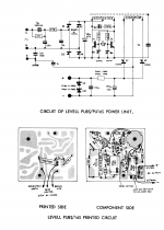
I tracked down a schematic of the original mains power supply Levell sold for this unit and it appears as if it would be much, much noisier than your design.
I shall compare the noise floor to the figures above and see, but I am much reassured that it will be fine.
It already includes one: it is an AC-coupled instrument.
You would need to add one if you work on very high voltage tube circuits, but for normal, semiconductor use, the internal one is sufficient (and it is well shielded).
IIRC, the capacitor has a 400V rating
Thank you, there are some mutterings about a maximum of around 25-30V on the highest frequencies in the manual and I wondered if an extra cap was advisable.
In principle, for general audio work you need an ~audio bandwidth, but to analyze specifically power supplies, a more limited range like 10 - 350Hz makes sense: That's where most of the noise is, and even if higher frequency noise is present, it matters less, because preamps etc. include some basic supply filtering, effective at high frequencies.
With SMPS, the sheer level of crap can cause whizzing and whistling even if the switching frequency is ultrasonic, because of intermodulation, and measuring a wider range makes sense
Thank you, this instrument, especially if not dependent on the silly battery is more than good enough for my purposes. I have measured a noise level of around 78-82uV of broadband noise, 11-12uV of 10Hz-350Hz noise on the positive rail of the LM7812/LM7912 PSU i use for my preamp. Given your use of this meter I will have built the denoiser right if the meter can't detect it over the noise floor. Time to build a new PSU entirely, thanks again for all your help.
Attachments
It is probably due to an excessive dissipation in the protection components with HF.Thank you, there are some mutterings about a maximum of around 25-30V on the highest frequencies in the manual and I wondered if an extra cap was advisable.
Frequency-meters generally have the same kind of limitations.
What you need for high amplitude/HF is an additional series resistor, not a capacitor
Hello, I would like to have a go at building the Nonoiser. Does anyone perhaps have the gerbers that Jackinnj refers to in this post:
I tried PM-ing him, but haven’t received a reply. Or gerbers for just the 317-circuit would also be great.
I will email the gerbers to anyone who PM's
I tried PM-ing him, but haven’t received a reply. Or gerbers for just the 317-circuit would also be great.
Last edited:
thank you
appreciated very much
appreciated very much
RV sets output voltage. R2 is part of RC filter and it’s value should be as high as possible but maintaining reasonable voltage drop and dissipated power.
BOM with values optimized for 5V output is in the attachment. According to the LTSpice simulation, with these values regulator achieves over 140 dB PSSR (surely somewhat less in practice).
Optimal dienioser values are different for various output voltages. With BC transistors, output noise level could be less than 0,5 µV and with ZTX ones less than 0,1 µV. Output impedance is in range of µ ohms.
Suggested part numbers in the BOM list are by no means exclusively acceptable or best possible. The most critical part is C8. It has to have ESR in certain range. To low or to high value and regulator could oscillate. That’s why there is a position for resistor in series with C8 so ESR can be adjusted and it is possible to use long life, low ESR, big value capacitors.
We all would very welcome your input on how does this regulator sonically compare to Salas shunt regulators and other types. IIRC you have build your own version of shunt regulators and some other types.
The Dienoiser has performances broadly similar to the nonoiser, if it is implemented with Kelvin connections.Hello, I would like to have a go at building the Nonoiser. Does anyone perhaps have the gerbers that Jackinnj refers to in this post:
I tried PM-ing him, but haven’t received a reply. Or gerbers for just the 317-circuit would also be great.
You could use it instead (I think someone published gerbers somewhere).
Both have their own peculiarities, and both are somewhat finicky, like most of high-perf circuits.
I have little experience with the Dienoiser, I just built a breadboard version, to make sure it could work, and have an idea about the size required for the compensation cap.
You should only use these regulators if you really need their performances, and if you are experienced enough to handle them properly, otherwise you must be prepared for frustration and disappointment: these are not easy, tolerant circuits like the denoiser (when used with a regular 317; other regs are something different)

It is OK with three remarks:
LM337 needs resistor (probably 33R) in series with C14 for stability
Output capacitor should be 100 µF with ESR in range 180 – 300 mΩ, or you can add small resistor in series with C17 & C18 and use big capacitors (low ESR)
D11 and D12 can be 1N4148
LM337 needs resistor (probably 33R) in series with C14 for stability
Output capacitor should be 100 µF with ESR in range 180 – 300 mΩ, or you can add small resistor in series with C17 & C18 and use big capacitors (low ESR)
D11 and D12 can be 1N4148
- Home
- Amplifiers
- Power Supplies
- D-Noizator: a magic active noise canceller to retrofit & upgrade any 317-based V.Reg.