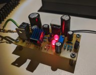
So actually I installed the 2N5551 the wrong way. I made the pcb with a BC337 footprint, and while quickly checking the 2N5551 datasheet I saw that the base is in the middle, but C and E are swapped. Installing the 2N5551 the right way seems to make it work right, and also doesn't need any compensation! Seems stable without any compensation.
I didn't have any MJE15033 PNP transistor, so I used the best I had according to sim, 2SB649. I'll test BD140 as well and maybe a few others I have. I will get a MJE15033 when I get the chance.
The performance seems to match the simulation, at least for PSRR. For noisefloor it seems the same as the previous discrete design. I'm not sure if it should be lower, as the .noise sim shows similar noise, but trying the self-noise sim as the other LM3x7 sims shows it should have a lower one. I'm not sure if this is due to my measuring setup, or I need to put the board in a case to get a lower noise floor.
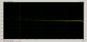
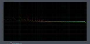
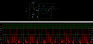
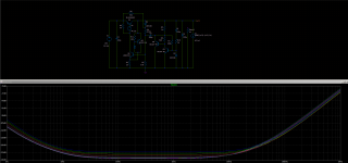
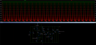
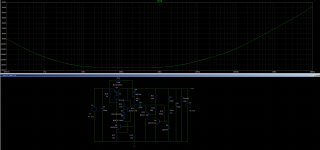
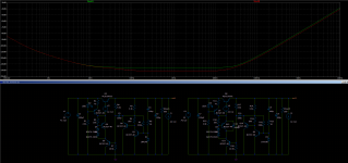
I attached few photos, first is the measurement without the capacitance multiplier in circuit (with it it looks the same as the other ones, nothing above the noisefloor). The second photo is a comparison between the first discrete design with positive feedback. Yellow trace is the latest design, red trace is the previous one. The input ripple is around -3dB to 0dB so the attenuation factor is the value on the graph with the extra -60dB from the LNA.
Output voltage is 11V, output current around 100mA total.
I'll test more the following days. But this looks very good! Second discrete design + denoiser.
edit: I used two random red leds. I'll try with LM329 as well, should have better tempco but higher noise. Also maybe the potentiometer is not the best for lowest noise, but very convenient for setting output voltage. With MJE15033 it should push -140dB for PSRR.
I didn't have any MJE15033 PNP transistor, so I used the best I had according to sim, 2SB649. I'll test BD140 as well and maybe a few others I have. I will get a MJE15033 when I get the chance.
The performance seems to match the simulation, at least for PSRR. For noisefloor it seems the same as the previous discrete design. I'm not sure if it should be lower, as the .noise sim shows similar noise, but trying the self-noise sim as the other LM3x7 sims shows it should have a lower one. I'm not sure if this is due to my measuring setup, or I need to put the board in a case to get a lower noise floor.
I attached few photos, first is the measurement without the capacitance multiplier in circuit (with it it looks the same as the other ones, nothing above the noisefloor). The second photo is a comparison between the first discrete design with positive feedback. Yellow trace is the latest design, red trace is the previous one. The input ripple is around -3dB to 0dB so the attenuation factor is the value on the graph with the extra -60dB from the LNA.
Output voltage is 11V, output current around 100mA total.
I'll test more the following days. But this looks very good! Second discrete design + denoiser.
edit: I used two random red leds. I'll try with LM329 as well, should have better tempco but higher noise. Also maybe the potentiometer is not the best for lowest noise, but very convenient for setting output voltage. With MJE15033 it should push -140dB for PSRR.
Attachments
Last edited:
You can lower the noise floor and improve the performances by bypassing Q27.edit: I used two random red leds. I'll try with LM329 as well, should have better tempco but higher noise. Also maybe the potentiometer is not the best for lowest noise, but very convenient for setting output voltage. With MJE15033 it should push -140dB for PSRR.
Since it is a LDO topology, it is normal to have a drop of ~Vcesat
Good morning all, I followed the thread from time to time but I can't find the part where is shown the right pcb routes relating to Kelvin connections for the denoiser (or nonoiser).
I read there are 4 separated paths (sense/force) at the output, but in another post it's said 3.
Anyone can help with that?
Thanks in advance
I read there are 4 separated paths (sense/force) at the output, but in another post it's said 3.
Anyone can help with that?
Thanks in advance
You can lower the noise floor and improve the performances by bypassing Q27.
Since it is a LDO topology, it is normal to have a drop of ~Vcesat
It seems the LM329 variant benefits the most from this, but not by much, around 5dB or so. And I had to use a 470uF cap, but 1000uF would cover the audio spectrum better.
The best compromise for noise and tempco seems to be a normal 6.2V Zener. I think LM329 is an IC? With it it wouldn't be a full discrete regulator.
Negative version with MJE15032 has a bit lower performance. I guess one could use two positive versions with dual secondaries. For the negative version one would have to just flip all polarities and replace each bjt with its complementary, same pcb could be used.
Simulation shows some instability without compensation for denoiser. I might add 33nF/4.7R on the pcb to be on the safe side. If there's anything happening it doesn't seem to affect the audio spectrum that I can measure. I still have to measure with an amp attached.
I'm also curious about trying to push more current through the regulator. Would be great to get few amps out of it.
Wouldn't it be a good idea to start a new thread? It was a long and bumpy but interesting road but after 200 pages it is now about a discrete built low noise LDO regulator.
I'll consider starting a new thread on the discrete versions, but I wanted the info to be here since it's made with the denoiser. The regulators themselves already exist in one form or another, I just augmented them with the denoiser and GLED blocks. Something like the LM317 and other regulator ICs that were augmented with the denoiser. Me and the thread creator considered this to be a good idea, to have this info here. Others may be inspired by the info to apply the denoiser in different ways.
I also want to make some more measurements before I consider the latest discrete version worthy of a separate thread.
Good morning all, I followed the thread from time to time but I can't find the part where is shown the right pcb routes relating to Kelvin connections for the denoiser (or nonoiser).
I read there are 4 separated paths (sense/force) at the output, but in another post it's said 3.
Anyone can help with that?
Thanks in advance
There's two wires, Vout and GND sense. The third might be related to the shields for coax used for each of the sense lines, which should be connected to ground close to the regulator.
Actually adding 30nH to the output cap specs seems to clear any instability issues in simulation. No need for compensation network for denoiser. Might be why I didn't notice anything at first measurements. I used a rather tall output cap which might have some ESL.
edit: ESR of output cap doesn't seem to matter. Results are similar with 50mOhm and 200mOhm.
edit: ESR of output cap doesn't seem to matter. Results are similar with 50mOhm and 200mOhm.
Last edited:
So, after 200 pages, how does it sound?
To say anything about any practical outcome, we should have a matured and proven schematic and a number of builders. I'm a volunteer for being a builder but when the compensation and output capacitor type selections, different concepts for different reg type came into play, I couldn't follow the thread anymore.
What we need as an outcome for this thread:
1. An analog dual rail (eg: +/-15V) for preamps, opamps etc.
2. Single low voltage positive reg (eg: +5v, +3.3V) for analog and digital sections for DAC chips.
@Trileru doing good job for contributing the thread but pace is so fast so a particular concept can't get enough attention from others for collaborating. I guess people like me watching the thread like "What is going on?"
So, after 200 pages, how does it sound?
You can get an idea by a.c. coupling the output of the "de-noised" regulator to a low THD signal source and looking at the FFT on the output supply rail.
I mentioned few pages back that it improved my DAC and headphone amp. I also have a DAC pcb that I'm waiting for. I designed it with LT3082+dienoiser for all 5 positive rails and LM337+dienoiser for the negative. I should have gotten it few days ago, but instead the courier gave me a jacket. Which curiously also fits me. So now I have to wait again for snailmail and hope this time they don't mix the packages again.
If you are talking about the discrete supply, I think it would be rather boring directly listening to its output. I could probably hear my thoughts.
To say anything about any practical outcome, we should have a matured and proven schematic and a number of builders. I'm a volunteer for being a builder but when the compensation and output capacitor type selections, different concepts for different reg type came into play, I couldn't follow the thread anymore.
What we need as an outcome for this thread:
1. An analog dual rail (eg: +/-15V) for preamps, opamps etc.
2. Single low voltage positive reg (eg: +5v, +3.3V) for analog and digital sections for DAC chips.
@Trileru doing good job for contributing the thread but pace is so fast so a particular concept can't get enough attention from others for collaborating. I guess people like me watching the thread like "What is going on?"
There's both versions that you described, in tht and smd version, single and dual. I tested the tht single, and smd dual, but the others are mirrored and contain the singles.
What I am waiting for is people making them and asking questions, which didn't really happen. Some might have built them and enjoy them.
For LM317 +dienoiser I think I mentioned many times: Panasonic FC 100uF/63V works fine, for LM337 I don't remember but I think I mentioned some models also.
I clearly mentioned the working output cap network values. 22uF ceramic + 30-50mOhm resistor + 30nH inductor (can be diy-ed). I think I updated the designs with smd footprints for this, so you have more control over each value if you don't want to use a single electrolytic that has these specs.
I do have a certain cap model (Panasonic something) that I got to test for LM337/LT3082 + dienoiser. I expect it to work, but will get to it when I'll assemble the DAC pcb.
To me it seems like a really low risk project. I expected more people to try and build them and ask questions.
Either way at worst you're getting a LM3x7 + denoiser working supply as I've tested the designs of interest. The denoiser doesn't need any special considerations and it offers most of the performance gains.
I built most supplies I tested with whatever I had laying around.
I might at some point do a recap post in which I post the designs of interest with info, but that would eat some time which I try to dedicate to other things in my life at this moment.
Seems that I can get 2A out of it but the output sags a bit. The output impedance stays real low, why does it sag like this? It's even worse with a resistive load.
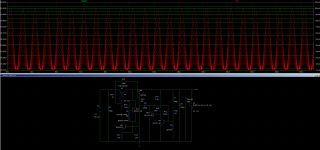
In this configuration R3 dissipates 1W in heat, and Q5 should be replaced with something like a TO-126 package as it dissipates around 1.5W. Performance seems to hold at 2A. The only issue seems to be the drooping output voltage, especially when I test with a resistor as a load.
The photos are with a stepped AC current load, 100mA to 2A.
edit: seems like more powerful transistors help with lowering the droop.
also higher voltage lower current seems to work fine. I simulated a version for around 68Vout and results seemed good.
Attachments
Last edited:
Yes I think it should be doable. What max current do you need?
I simulated for 68Vout with very good performance. This supply should be very flexible, and cheap.
Current up to 100mA, it should be more than enough.
")
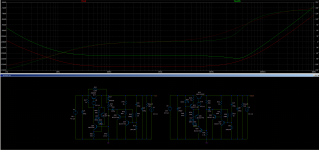
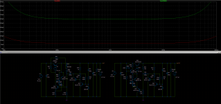
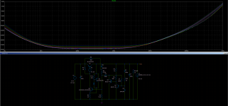
For some reason with these values there's even better performance. I added a simple Zener part that I could also find a spice model for. It could be replaced with a 12V variant. Tempco seems pretty good also.
The resistor divider could be replaced with a 20k pot for fine adjustment.
edit: spice model is from Nexperia website.
The resistor divider could be replaced with a 20k pot for fine adjustment.
edit: spice model is from Nexperia website.
Attachments
Last edited:
Showing a denoiser applied to any kind of regulator, be it monolithic, discrete or hybrid is certainly not a problem, and falls within the scope of the original thread but if a complete generation of discrete regs stems from the original thread, it should be discussed in its (their) own space(s).Wouldn't it be a good idea to start a new thread? It was a long and bumpy but interesting road but after 200 pages it is now about a discrete built low noise LDO regulator.
There are at least two types of discrete regs now discussed, and they are very different: one is based on an unusual, bootstrap/positive feedback principle and the other is a more classical error-amplifier type with a denoiser added.
I think they both deserve attention, but each one should have its dedicated thread since they operate on opposite principles.
(I am not trying to exile Trileru from this thread, his abundant contributions are extremely welcome, and I thank him for that, but for the sake of clarity, some order is needed, because some members are beginning to be lost in the many bifurcations)
Last edited:
After I get the three pin reg pcbs and test them I'll make a post in which I'll aggregate the info and designs so we have a reference post for pcb designs and info on component values etc. This way we could easily refer people to it. Truth be told there's a lot of info around the denoiser and different regulators it can be successfully applied to.
I also have to test the coax sense lines vs normal wires. I think after this I've gone through most important stuff.
I also have to test the coax sense lines vs normal wires. I think after this I've gone through most important stuff.
@Trileru
One of the other things that I have to notice is, when you are giving some technical info, you are using long sentences like telling some story. Generally, technical sentences appears to be short and effective. Otherwise people can't easily pick important information.
I advice you to use bullet listing type information with a header when giving some important information or some specific values. e.g:
Dienoiser:
Reg: TI LM317N
Cout: 220uF (may give a range) AL (ESR ~ 0.1-0.5) or 22uF MLCC + 0.02R + 30nH
R1: ...
Since schematic is straight forward, people may decide to build on a protoboard as long as component list is known. I know, a tested PCB is much better but builders may want to tryout a working/tested schematic at first. Later they may put a full effort on a nice looking PCB version.
Last edited:
For some reason with these values there's even better performance. I added a simple Zener part that I could also find a spice model for. It could be replaced with a 12V variant. Tempco seems pretty good also.
The resistor divider could be replaced with a 20k pot for fine adjustment.
edit: spice model is from Nexperia website.
Great, thanks. I'll try it.
Regards
You can lower the noise floor and improve the performances by bypassing Q27.
Seems like the positive feedback version benefits more from this. Also seems that both designs do better for PSRR with higher voltages.
1000uF seems to cover down to 100Hz, and now it offers -140dB at 100Hz. 30Vout and 100mA. Output impedance is also lowered.
Attachments
- Home
- Amplifiers
- Power Supplies
- D-Noizator: a magic active noise canceller to retrofit & upgrade any 317-based V.Reg.