I've checked the datasheet but cannot find anything with respect to this matter.
Here is the question:
Is the thinner part of the LM3886TF chip, the part where the screw hole is located, empty and only used for mounting or are there any electronics in this part?
The reason being that I would like to cut a part of for mounting purposes. The chips will be mounted with a heat spreader bar and I will not use the screw hole. In stead I have just not enough space for the height of the chip and if I can saw the upper part, say upto the mid of the screw hole, off than I can fit the amps in the desired case.
Maybe a strange question though I cannot see a reason not to try🙂
Well for sure it is electricaly connected to the chip... guess you can cut some off, but I would derate the unit a little then... and aim to keep power a little bit further away from maximum as you now have a smaller heat transfer area from the case to the heatsink...
I will use the chips with 18V tranny (25V DC) so they are not up to the max power potential. There will be an aluminium heat spreader bar or cooling element on the front of the chips to keep them as cool as possible under the circumstances. My guess is that most of the heat is generated in the area where the electronics are
Yep... but its not realy designed to go through the plastic would be my guess... most heat will move through the metal parts... to front part is more like a dome over the chip...
Oh well even if it burns up... you can probably still afford a few meals for the month...
Oh well even if it burns up... you can probably still afford a few meals for the month...
There are no electronic components in the thin area. Given your proposed solution for mounting, I would say you have a high probability of a successful installation.
Two things to consider after you make the cut.
1. You will be exposing a metal tab underneath the plastic which is electrically connected to the chip. Make sure the exposed metal has enough clearance from your heatsink / enclosure to avoid a short.
2. After you cut, bevel the cut edge with some sandpaper or a file so that burrs from the cut plastic and metal do not prevent the part from sitting flat on the heatsink.
Good luck!
David
Thanks Guys,
It is a TF chip, so no metal parts currently exposed. I will isolate the metal parts if they become exposed. If it is only the metal part I'm not worried, I was worried about electronics that might be exposed and/or damaged.
Calculated maximum power dissipation will be at 28 watt maximum with this relatively low voltage and the predicted loudspeaker impedance(4 ohm) and a maximum power rating of 50W output per chip.
I would not try this ussually but I want to pack the amplifier with PSU and remote controls for source selection and volume control in a really small case
I can't see any problem in cutting off part of the exposed metal. What you do want to be careful of is warping the part, as that will crack the die mounting. Look at the torque specs for mounting flat pack devices- they're quite low for a reason. I'd not try this with a hack saw, but use a jewelers saw with a medium blade. Far less stress on the part.
fwiw. I attempted to cut the tab off of a voltage regulator a while back to make it fit a case. Unfortunately it did not work after the event.
There is no way back now🙂
It looks like the operation was successful. It will be a while before I can test them though but I will let you know when and if it works
The chips will be in between aluminium, there will be a small heatsink on the front, a part of an 486 processor cooler.
Pics to follow
It looks like the operation was successful. It will be a while before I can test them though but I will let you know when and if it works
The chips will be in between aluminium, there will be a small heatsink on the front, a part of an 486 processor cooler.
Pics to follow

The power supply will be in the same box. For now I think I will use a 160Va tranny.
The problem will be the remote volume control and remote source selection.
The box isn't that small, it is 15cm*16,5cm*5cm but it will be crowded😎
The problem will be the remote volume control and remote source selection.
The box isn't that small, it is 15cm*16,5cm*5cm but it will be crowded😎
That heat is probably too small for a single chipamp, never mind two of them.
How will the air flow cool your sink?
How will cold air get in and hot air get out of your enclosure and flow along the fins of the sink?
How will the air flow cool your sink?
How will cold air get in and hot air get out of your enclosure and flow along the fins of the sink?
Delete the word "probably"!AndrewT said:That heat is probably too small for a single chipamp,....

AndrewT said:That heat is probably too small for a single chipamp, never mind two of them.
How will the air flow cool your sink?
How will cold air get in and hot air get out of your enclosure and flow along the fins of the sink?
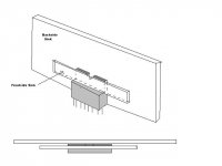
It appears that the case itself is a heat sink and will provide most of the cooling. The black heat sinks you see in the photo will be used to hold the chips to the case, as a clamp across the face of the chips. If that is how he's doing planning on proceeding it may work fine.
Sherman, that's correct. The small heatsink strip is just to hold the chips properly and provide some additional cooling too. The aluminium case will perform as heatsink. The complete cover and bottem is perforated plate but the main cool element will is the side and front/rear of the case.
I've recently tested an amp with two LM3875's in an even smaller box whit no perforation at all. The amp was driven hard for several (4) hours at 70-80% of the maximum. The LM3875 are not driven to the max because the tranny is only 120Va but DC on the chips is +/-36V. The case was getting quite hot to the tough but my guess is that it was still below 60% celsisus. The whole casing functions as a heatsink.
I've posted a photo from this amp on this forum quite a while ago.
edit: typo and here is the picture of the case http://www.diyaudio.com/forums/showthread.php?postid=821416#post821416
The hum problems was completely solved.
- Status
- Not open for further replies.
- Home
- Amplifiers
- Chip Amps
- Cutting off a piece of an LM3886 (yes, with a saw)