Hi Everyone!
Like several folks who have posted on DIYAudio, I decided to build a pair of the Joe D’Appolito Thor speakers years ago when the AudioXpress article came out, in May 2002. While the drivers weren’t inexpensive, the reputation of the designer and the well-written article seemed to make it a safe bet (if interested see the original article, courtesy Madisound’s website: http://www.madisound.com/loudspeaker_specifications/audioXpress Thor Review.pdf).
Unfortunately I wasn’t all that happy with the speaker when I finished the project. I found it to be lean and dry in the bass, though the midrange and treble were pretty good. Wasn’t quite up to the glowing review in AudioXpress, though, which was disappointing to say the least.
So having invested in the SEAS drivers, I decided to build the Odin version, thinking the problem could be with the transmission line. My hope was a more conventional base reflex design would be an improvement. With a smaller speaker, I would be able to supplement bass response with a sub if bass quality and extension still fell short. And indeed, I did find the Odin’s to have better quality bass, though still on the lean side.
So then I built a pair of 10” subwoofers, w/10” passive radiators, exactly the same external size as the Odins, stacking the Odins on top the subs. As you might imagine that’s not such an easy trick to pull off, so while it worked I subsequently put the Odin’s on stands and moved the subs to the sidewalls. This turned out to be a pretty good setup, with the ability to dial in bass extension via the subs by modifying the low pass filter point and volume control in my electronic crossover.
More recently last year I retired and moved to Oregon, and built a house which has a dedicated listening room, designed to the Golden Ratio. (This new room is wonderful and if you ever have the luck to build a dedicated listening/media room, be sure and use Golden Ratio proportions).
In an effort to get even better bass and balance in my system, I decided to look around for a new speaker project, and began searching on DIYAudio – and low and behold, found out there were others who had the same problems I’d had with the original Thor design! So thanks to all the great threads and shared work by Scottmoose, Planet10, Renron and others (thanks tons, guys!!), I became inspired to go for another Thor build.
My design goals are:
1) The new speaker has to be esthetically pleasing! Design and quality of the woodworking are very important.
2) The furniture in my new listening room sits folks on the low side, so I didn’t want the speaker to be any higher than 50".
3) I also wanted a tower concept, so the small Thor is about right. I would be retaining my subwoofers so the ability to dial in supplemental deep bass would not be a problem.
4) My current speakers sit 28-30” from the back wall, and ~38” from the sidewalls of my media room. I wanted to keep the same positioning, more or less.
I’ve always found curved speakers visually appealing, so I decided to follow in Renron’s footsteps and build a curved version of the Small Thor. Thanks to his excellent thread and pictures, I spent several months thinking through the construction details and drafted up this version of what Ron did, attached. Thanks for the inspiration, Ron!
I solicited help during the design phase from Planet10 and got lots of great suggestions and feedback – thanks again for all your comments, Dave!!
One design issue was where to put the crossover. I originally though about putting them in a box on the back of the speaker, but going with a curved design is problematic, the back is not wide enough and it is hard to make that esthetically pleasing. If I put in a false base or false top I’d have to raise the speaker another 3+”, which would make it too tall.
One obvious solution is to put them in a box on my equipment stand and run the driver wires to the speaker, but I’d really rather have them inside the speaker to reduce clutter – my equipment stand is already overloaded. So I made provision to mount them on the inside front baffle, but plan to test if this makes a difference by performing listening tests with the xovers both in and out of the speaker, running the wires through the port for the external test.
The other main issue was where to put the port, since in this design it could be out the front, the bottom or the back. The front was eliminated because I needed access to the crossover mount point. Down-firing out the bottom would require lifting the speaker higher, and I didn’t want to do that – so the practical solution was to go with a rear firing port. My speakers will be positioned well away from the back and side-walls, so hopefully excessive boomy bass will not be a problem.
In order to understand how much room I needed for the crossover, I decided to build it first. In researching the numerous Thor threads, jimangie1973 has spent a lot of time and effort redesigning and tweaking his crossover design. Jim is clearly another hero in the efforts to improve on the original D’Appolito design. Attached is Jim’s last and final? design.
According to Jim in a PM, the latest crossover “…has slopes closest to LR4. The added RLC on tweeter is there to counter the tweeter resonance impedance spike to keep the response LR4. Without, there is less attenuation around the resonance. Power handling is improved as a result of the added attenuation.” Jim will hopefully comment further on this post.
“The earlier designs had slightly too much baffle step compensation. The result was over time I perceived the sound as slightly bass heavy. This is the main change in the woofer section.”
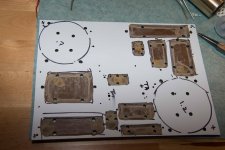
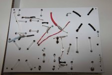
Here are some pics of my crossover – I built it using ¼” phenolic board, and routed out depressions for the caps and inductors, which were subsequently mounted on thin rubber sheet glued in with RTV and held in place with cable-ties.
Enough for now - more later - your comments welcome! ;~)
Like several folks who have posted on DIYAudio, I decided to build a pair of the Joe D’Appolito Thor speakers years ago when the AudioXpress article came out, in May 2002. While the drivers weren’t inexpensive, the reputation of the designer and the well-written article seemed to make it a safe bet (if interested see the original article, courtesy Madisound’s website: http://www.madisound.com/loudspeaker_specifications/audioXpress Thor Review.pdf).
Unfortunately I wasn’t all that happy with the speaker when I finished the project. I found it to be lean and dry in the bass, though the midrange and treble were pretty good. Wasn’t quite up to the glowing review in AudioXpress, though, which was disappointing to say the least.
So having invested in the SEAS drivers, I decided to build the Odin version, thinking the problem could be with the transmission line. My hope was a more conventional base reflex design would be an improvement. With a smaller speaker, I would be able to supplement bass response with a sub if bass quality and extension still fell short. And indeed, I did find the Odin’s to have better quality bass, though still on the lean side.
So then I built a pair of 10” subwoofers, w/10” passive radiators, exactly the same external size as the Odins, stacking the Odins on top the subs. As you might imagine that’s not such an easy trick to pull off, so while it worked I subsequently put the Odin’s on stands and moved the subs to the sidewalls. This turned out to be a pretty good setup, with the ability to dial in bass extension via the subs by modifying the low pass filter point and volume control in my electronic crossover.
More recently last year I retired and moved to Oregon, and built a house which has a dedicated listening room, designed to the Golden Ratio. (This new room is wonderful and if you ever have the luck to build a dedicated listening/media room, be sure and use Golden Ratio proportions).
In an effort to get even better bass and balance in my system, I decided to look around for a new speaker project, and began searching on DIYAudio – and low and behold, found out there were others who had the same problems I’d had with the original Thor design! So thanks to all the great threads and shared work by Scottmoose, Planet10, Renron and others (thanks tons, guys!!), I became inspired to go for another Thor build.
My design goals are:
1) The new speaker has to be esthetically pleasing! Design and quality of the woodworking are very important.
2) The furniture in my new listening room sits folks on the low side, so I didn’t want the speaker to be any higher than 50".
3) I also wanted a tower concept, so the small Thor is about right. I would be retaining my subwoofers so the ability to dial in supplemental deep bass would not be a problem.
4) My current speakers sit 28-30” from the back wall, and ~38” from the sidewalls of my media room. I wanted to keep the same positioning, more or less.
I’ve always found curved speakers visually appealing, so I decided to follow in Renron’s footsteps and build a curved version of the Small Thor. Thanks to his excellent thread and pictures, I spent several months thinking through the construction details and drafted up this version of what Ron did, attached. Thanks for the inspiration, Ron!
I solicited help during the design phase from Planet10 and got lots of great suggestions and feedback – thanks again for all your comments, Dave!!
One design issue was where to put the crossover. I originally though about putting them in a box on the back of the speaker, but going with a curved design is problematic, the back is not wide enough and it is hard to make that esthetically pleasing. If I put in a false base or false top I’d have to raise the speaker another 3+”, which would make it too tall.
One obvious solution is to put them in a box on my equipment stand and run the driver wires to the speaker, but I’d really rather have them inside the speaker to reduce clutter – my equipment stand is already overloaded. So I made provision to mount them on the inside front baffle, but plan to test if this makes a difference by performing listening tests with the xovers both in and out of the speaker, running the wires through the port for the external test.
The other main issue was where to put the port, since in this design it could be out the front, the bottom or the back. The front was eliminated because I needed access to the crossover mount point. Down-firing out the bottom would require lifting the speaker higher, and I didn’t want to do that – so the practical solution was to go with a rear firing port. My speakers will be positioned well away from the back and side-walls, so hopefully excessive boomy bass will not be a problem.
In order to understand how much room I needed for the crossover, I decided to build it first. In researching the numerous Thor threads, jimangie1973 has spent a lot of time and effort redesigning and tweaking his crossover design. Jim is clearly another hero in the efforts to improve on the original D’Appolito design. Attached is Jim’s last and final? design.
According to Jim in a PM, the latest crossover “…has slopes closest to LR4. The added RLC on tweeter is there to counter the tweeter resonance impedance spike to keep the response LR4. Without, there is less attenuation around the resonance. Power handling is improved as a result of the added attenuation.” Jim will hopefully comment further on this post.
“The earlier designs had slightly too much baffle step compensation. The result was over time I perceived the sound as slightly bass heavy. This is the main change in the woofer section.”
Here are some pics of my crossover – I built it using ¼” phenolic board, and routed out depressions for the caps and inductors, which were subsequently mounted on thin rubber sheet glued in with RTV and held in place with cable-ties.
Enough for now - more later - your comments welcome! ;~)
Attachments

Having previously used MDF for speaker projects, I'm making the switch to baltic birch for the front, back, and internal braces after researching materials on the forum. I've got to say it is a lot nicer to work with than MDF. The exterior will be finished in cherry, and I'm cutting my own veneers on the bandsaw. The front baffle will have 1/8" cherry laminated to 3/4" & 1/2" BB. The edges of the baffles are trimmed with 1"x1" cherry, which will have a 1" roundover applied once the internal braces and ribs have been fitted.
The back is built up to 1" thickness. The sides will be 5mm bendy plywood, supported by ribs rabbeted into the internal braces, and will also be built up to 1" thickness by laminating multiple sheets, ending with 3/32" cherry veneers with the grain laying horizontally.
This pic shows one of the front baffles after machining the driver cutouts, with the back prior to cutting the port etc.

These show the beginning construction of the internal braces. On the back of the front baffle is a recess fitted for the crossover - will show a detailed pic of that later.


The back is built up to 1" thickness. The sides will be 5mm bendy plywood, supported by ribs rabbeted into the internal braces, and will also be built up to 1" thickness by laminating multiple sheets, ending with 3/32" cherry veneers with the grain laying horizontally.
This pic shows one of the front baffles after machining the driver cutouts, with the back prior to cutting the port etc.
These show the beginning construction of the internal braces. On the back of the front baffle is a recess fitted for the crossover - will show a detailed pic of that later.
... switch to baltic birch... I've got to say it is a lot nicer to work with than MDF.
And it should sound better
")
dave
Progress pics. The back of the front baffle:

The internal braces have been 'swiss-cheesed' and other support pieces and the ribs are being fitted in. The support pieces and ribs all slide into the rabbets. My dog Duke closely supervises all steps.


These are the ribs - they slide into the dado joints, and once glued in place will hopefully form strong null points, providing additional bracing of the side panels to the internal structure.

A pic of the jig I used to make the curved sections. Very simple, used 1/16" drill bits to scribe the curve into the wood.

Still need more sanding and fitting of individual parts. Next step is fitting the back, installing the port tubes and the binding post plates. Should be able to start gluing parts together this weekend.
The internal braces have been 'swiss-cheesed' and other support pieces and the ribs are being fitted in. The support pieces and ribs all slide into the rabbets. My dog Duke closely supervises all steps.
These are the ribs - they slide into the dado joints, and once glued in place will hopefully form strong null points, providing additional bracing of the side panels to the internal structure.
A pic of the jig I used to make the curved sections. Very simple, used 1/16" drill bits to scribe the curve into the wood.
Still need more sanding and fitting of individual parts. Next step is fitting the back, installing the port tubes and the binding post plates. Should be able to start gluing parts together this weekend.


Top Design - opinions needed!
One speaker design I really admire is the Sonus Faber amati futura. They are an Italian work of art, and at $36k not cheap! Their base design is a complex form of what I'm planning for my speaker, also used by a lot of manufacturers:

My plan is to use a modified version of this - here is a draft top view. I've found a metal worker in town who can transform my drawing into a CNC milled 1/4" powder coated steel plate (maybe brushed stainless?), from which I can mount my Parts Express cone footers. The plate would be easily attached using threaded brass insets, placed into the baltic birch bottom or side panels; screw bolts hidden underneath the speaker.

Now I'm wrestling with how to finish off the top. I was going to finish it with a milled piece of solid cherry, but I'm attracted to using a steel or non-ferrous 1/4" plate. The simplest way to attach this would be to epoxy it into place on the top of the baltic birch - a permanent way to go with no room for error. Alternatively the steel plate could be mounted on a thin piece of cherry to provide a more layered finish. Here's a pic of the amati futura top:

Any opinions?
One speaker design I really admire is the Sonus Faber amati futura. They are an Italian work of art, and at $36k not cheap! Their base design is a complex form of what I'm planning for my speaker, also used by a lot of manufacturers:
My plan is to use a modified version of this - here is a draft top view. I've found a metal worker in town who can transform my drawing into a CNC milled 1/4" powder coated steel plate (maybe brushed stainless?), from which I can mount my Parts Express cone footers. The plate would be easily attached using threaded brass insets, placed into the baltic birch bottom or side panels; screw bolts hidden underneath the speaker.
Now I'm wrestling with how to finish off the top. I was going to finish it with a milled piece of solid cherry, but I'm attracted to using a steel or non-ferrous 1/4" plate. The simplest way to attach this would be to epoxy it into place on the top of the baltic birch - a permanent way to go with no room for error. Alternatively the steel plate could be mounted on a thin piece of cherry to provide a more layered finish. Here's a pic of the amati futura top:
Any opinions?
Attachments
Ideally, relatively lightweight [< ~40 lbs] speakers need to be mass loaded to the floor, so I used thick marble, slate tops held on with industrial grade Velcro because at the time it was cheap and later either used metal or Portland cement tops as a base under the finished top and/or recommended placing a large/heavy potted plant on top. Smoked tempered glass was real popular back then because speakers tended to do double duty as a place to put drinks, ashtrays, food. Looks good too or use clear to add that super depth to a wood/whatever finish.
How much weight required depended on at what point I heard the speaker 'tighten up', for lack of a better description and any more tended to 'dull' its 'tone'. Never did any comparisons, but this assumes that the driver are mass loaded to the speaker as opposed to just baffle mounting them.
GM
How much weight required depended on at what point I heard the speaker 'tighten up', for lack of a better description and any more tended to 'dull' its 'tone'. Never did any comparisons, but this assumes that the driver
GM
Thanks for your thoughts - BB does have a much lower density than MDF, so these speakers will likely finish in around 40-50 lbs, I guess. I hadn't thought too much about the mass loading issue, but a steel top would help.
From the Sonus Faber's website the Amati Futura has "a Tuned Mass Damper, with multiple tuning frequencies, like on record skyscrapers and F1 cars converts the residual vibrations into heat (thermkinetics) by out-of-phase vibrations."

Looks like it is in a sealed compartment in the top of the speaker - very interesting idea. Looks like they use BB or similar in construction of their cabinet frame.
Perhaps adding more mass than 1/4" of steel plate on top would be a good idea?
From the Sonus Faber's website the Amati Futura has "a Tuned Mass Damper, with multiple tuning frequencies, like on record skyscrapers and F1 cars converts the residual vibrations into heat (thermkinetics) by out-of-phase vibrations."
Looks like it is in a sealed compartment in the top of the speaker - very interesting idea. Looks like they use BB or similar in construction of their cabinet frame.
Perhaps adding more mass than 1/4" of steel plate on top would be a good idea?
Yeah, if I can easily lift it, it's probably too light, well, when I was younger anyway.
Regardless, at least when using 3/4" BB, apple, marine plywood or seasoned hardwood, there's a point where more weight is too much with relatively small speakers, so no set weight. For large cabs like my ~20 ft^3 mains, they still sound the right amount of inert at ~245 lbs on a 'floating' hardwood covered 1x8 pine board sub floor, so guessing I'm 'tuning' it more than the cab.
GM
I'm thinking I'll go for the steel top, baring complications to ad more mass, thanks for the advice!
Currently gluing on the back and finishing gluing in the ribs. Can't have enough clamps!!


Next step will be fine tuning the driver installations.
One question I have is how best to mount the drivers...with gaskets or without? It seems folks have done it both ways.
My current thought is to use a thin foam gasket on the front baffle, with hard felt on the internal brace. The SEAS drivers have a rubber boot, so there is already some give when mounting the driver frame right up against the internal brace, but I worry that a hard mount could produce rattles if the wood shrinks or expands during seasonal variations.
Seems prudent to use something like the hard felt that can absorb a bit of compression.
Any thoughts?
Thanks!
Currently gluing on the back and finishing gluing in the ribs. Can't have enough clamps!!
Next step will be fine tuning the driver installations.
One question I have is how best to mount the drivers...with gaskets or without? It seems folks have done it both ways.
My current thought is to use a thin foam gasket on the front baffle, with hard felt on the internal brace. The SEAS drivers have a rubber boot, so there is already some give when mounting the driver frame right up against the internal brace, but I worry that a hard mount could produce rattles if the wood shrinks or expands during seasonal variations.
Seems prudent to use something like the hard felt that can absorb a bit of compression.
Any thoughts?
Thanks!
Are you talking about buying Sorbothane sheets to cut gaskets from?
Seems there are two schools of thought...one where you're attempting to isolate the driver from the cabinet, and the other to directly ground the speaker basket to the cabinet.
Has anyone tested these approaches in the same speaker?
Seems there are two schools of thought...one where you're attempting to isolate the driver from the cabinet, and the other to directly ground the speaker basket to the cabinet.
Has anyone tested these approaches in the same speaker?
The revised Thor design is intended to have driver reactive forces shunted away from the baffle thru the holey brace. Trying to isolate the driver from the baffle counteracts that.
Reports are that besides more bass, the holey driver brace leads to greater DDR, ie allows for less loss of detail.
dave
Reports are that besides more bass, the holey driver brace leads to greater DDR, ie allows for less loss of detail.
dave
Dave,
Expanding on what you said, you would favor :
1) use no gaskets to mount the driver,
2) then use wood shims to build up the brace, so when the driver is mounted there is some tension on the driver frame.
What about using a hard felt pad on the brace instead of direct wood contact? I could rely on the rubber boot on the back of the driver to provide some give.
1) use no gaskets to mount the driver,
I's use the factory gaskets, if they come with them. Otherwise, then thin closed cel foam weather strip (draught exclusion strip)
2) then use wood shims to build up the brace, so when the driver is mounted there is some tension on the driver frame.
You want it hard up against the magnet, but not hard enuff that you are stressing the basket, Also fo not overtighten the fixing screws/bolts.
What about using a hard felt pad on the brace instead of direct wood contact? I could rely on the rubber boot on the back of the driver to provide some give.
it is primarily the LF energy you want to shunt. Hard felt is probably fine. If we don;t get the brace perfect, we use woof shims of even paper. You want no give. I have a collection of rubber boots here.
dave


Test fitting the binding posts, port, and crossover inserted into its recess before the sides go on. The Small Thor build calls for a 3" port 4" long; unfortunately I did not have room for a 3" port on the back panel of this curved design. A Parts Express 2 1/2" port just fits - it is actually 2 5/8" diameter - it still needs to be cut down to 3" long to maintain the area/length ratio. Has a flange which makes mounting a snap.

For the crossover recess, I'm using 3 layers of rubber non-skid to ensure no rattles - one layer glued to the back of the baffle, and 2 layers glued to back of the crossover. Crossover held in place with 4 hex-head screws in the corners.

Besides testing the crossover mounted inside as well as outside the speaker, I'll also be comparing the latest jimangie1973 design against the Madisound crossover included in the Thor kit. Cost was $35/crossover, so I decided it might be worth making some listening test comparisons.

For the crossover recess, I'm using 3 layers of rubber non-skid to ensure no rattles - one layer glued to the back of the baffle, and 2 layers glued to back of the crossover. Crossover held in place with 4 hex-head screws in the corners.
Besides testing the crossover mounted inside as well as outside the speaker, I'll also be comparing the latest jimangie1973 design against the Madisound crossover included in the Thor kit. Cost was $35/crossover, so I decided it might be worth making some listening test comparisons.
I used closed cell foam gasket material around the baffle recess to install the woofer. That worked fine, compresses easily and providers a good seal for the speaker against the baffle.
But here's the hard felt I tried - used for protecting hardwood floors from furniture.

It compresses without distorting the speaker basket in any way, but is it stiff enough to firmly set the speaker frame against the driver brace?


Dave, do you use wood roof shims or asphalt shims? There are even thin metal shims for slipping behind cracked cedar shingles.
But here's the hard felt I tried - used for protecting hardwood floors from furniture.
It compresses without distorting the speaker basket in any way, but is it stiff enough to firmly set the speaker frame against the driver brace?
Dave, do you use wood roof shims or asphalt shims? There are even thin metal shims for slipping behind cracked cedar shingles.
It compresses without distorting the speaker basket in any way, but is it stiff enough to firmly set the speaker frame against the driver brace?
If it is like the stuff we use for the bottom of speakers, likely yes.
Dave, do you use wood roof shims or asphalt shims?
Chris does the construcioneering. He is pretty good with getting the holey braces close to perfect. Most I've ever had to use was a folded piece of paper.
dave
Sometimes laugh about how picky I am about this measure.
Have used 80# acid free paper and make a basket gasket shim. Sometimes use butyl rubber / duct rope caulk on the magnet for a dampening layer between the brace if force cancellation cannot be used.
Low frequency drivers not operating in the low midrange up can be and should be solid mounted. Midbasses and up should be isolated with something like sorbothane (cut from sheet if neccessary). Have used multiple layers of tar paper to good effect. Neoprene can be used for tweeters, but loose effectiveness as we hit the midrange. Important to note isolation requires special attention to mounting.
- Status
- This old topic is closed. If you want to reopen this topic, contact a moderator using the "Report Post" button.
- Home
- Loudspeakers
- Multi-Way
- Curved Small Thor Redux